- 您現(xiàn)在的位置:買賣IC網(wǎng) > PDF目錄98143 > ST10F168-Q3 (STMICROELECTRONICS) 16-BIT, FLASH, 25 MHz, MICROCONTROLLER, PQFP144 PDF資料下載
參數(shù)資料
| 型號: | ST10F168-Q3 |
| 廠商: | STMICROELECTRONICS |
| 元件分類: | 微控制器/微處理器 |
| 英文描述: | 16-BIT, FLASH, 25 MHz, MICROCONTROLLER, PQFP144 |
| 封裝: | 28 X 28 MM, PLASTIC, QFP-144 |
| 文件頁數(shù): | 33/74頁 |
| 文件大小: | 479K |
| 代理商: | ST10F168-Q3 |
第1頁第2頁第3頁第4頁第5頁第6頁第7頁第8頁第9頁第10頁第11頁第12頁第13頁第14頁第15頁第16頁第17頁第18頁第19頁第20頁第21頁第22頁第23頁第24頁第25頁第26頁第27頁第28頁第29頁第30頁第31頁第32頁當前第33頁第34頁第35頁第36頁第37頁第38頁第39頁第40頁第41頁第42頁第43頁第44頁第45頁第46頁第47頁第48頁第49頁第50頁第51頁第52頁第53頁第54頁第55頁第56頁第57頁第58頁第59頁第60頁第61頁第62頁第63頁第64頁第65頁第66頁第67頁第68頁第69頁第70頁第71頁第72頁第73頁第74頁
ST10F168
39/74
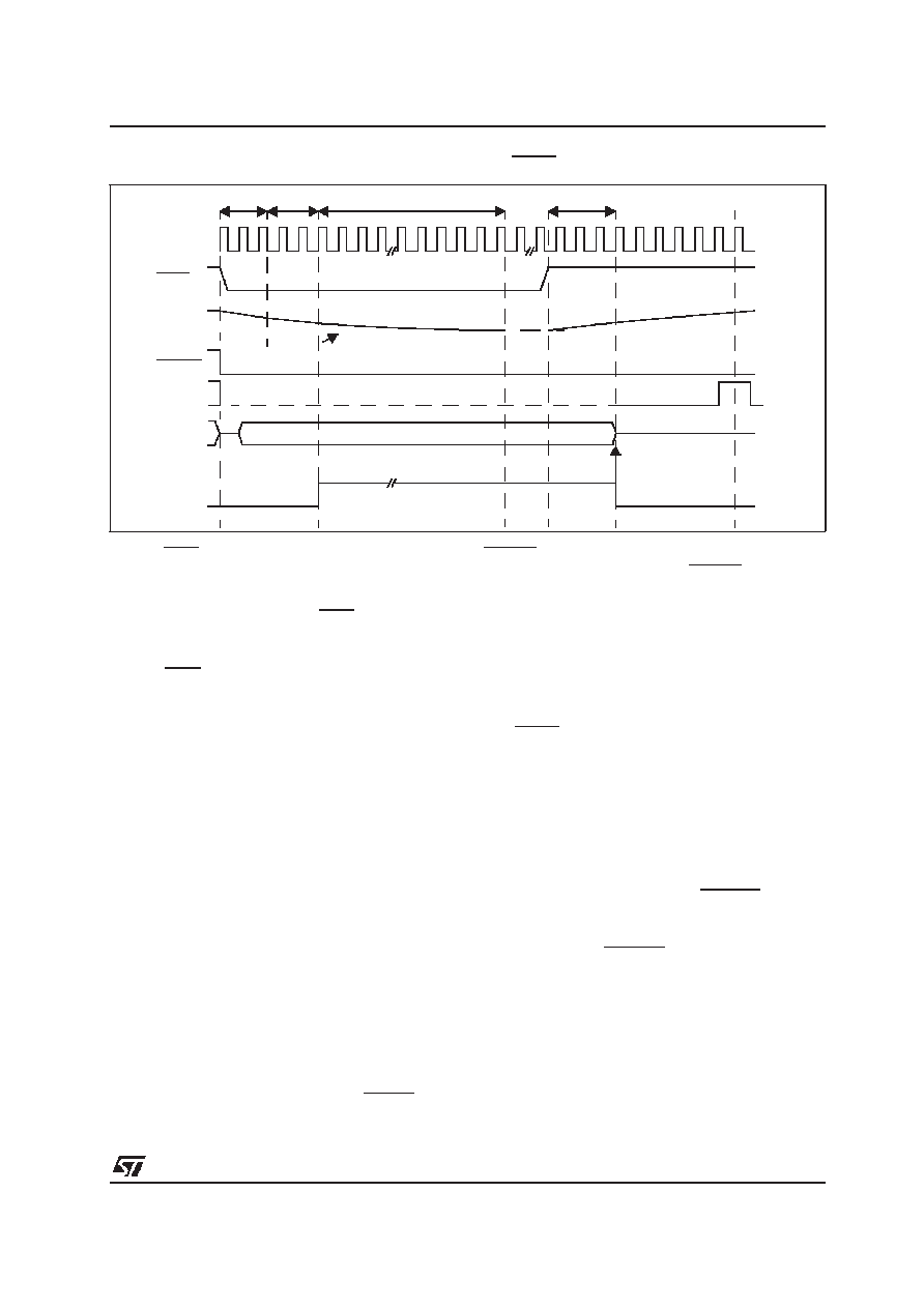
Figure 11 : Synchronous Warm Reset: Long low pulse on RSTIN
Notes: 1. RSTIN rising edge to internal latch of Port0 is 3CPU
clock cycles (6 TCL) if the PLL is bypassed and the
prescaler is on (fCPU =fXTAL / 2), else it is 4 CPU clock
cycles (8 TCL).
2. If during the reset condition (RSTIN low), Vpp voltage
drops below the threshold voltage (about 2.5V for 5V
operation), the asynchronous reset is then immediately
entered.
3. RSTIN pin is pulled low if bit BDRSTEN (bit 5 of
SYSCON register) was previously set by soft-ware. Bit
BDRST EN is cleared after reset.
17.3 - Software Reset
A software reset sequence can be triggered at
any time by the protected SRST (software reset)
instruction. This instruction can be deliberately
executed within a program, e.g. to leave bootstrap
loader mode, or on a hardware trap that reveals
system failure.
On execution of the SRST instruction, the internal
reset sequence is started. The microcontroller
behaviour is the same as for a synchronous reset,
except that only bit P0.12...P0.8 are latched at the
end of the reset sequence, while previously
latched, bit P0.7...P0.2 are cleared.
17.4 - Watchdog Timer Reset
When the watchdog timer is not disabled during
the initialization, or serviced regularly during pro-
gram execution, it will overflow and trigger the
reset sequence.
Unlike hardware and software resets, the watch-
dog reset completes a running external bus cycle
if this bus cycle either does not use READY, or if
READY is sampled active (low) after the pro-
grammed wait states. When READY is sampled
inactive (high) after the programmed wait states
the running external bus cycle is aborted. Then
the internal reset sequence is started.
Bit P0.12...P0.8 are latched at the end of the reset
sequence and bit P0.7...P0.2 are cleared.
17.5 - Reset Circuitry
Internal reset circuitry is described in Figure 13.
The RSTIN pin provides an internal pullup resistor
of 50K
to 250K (The minimum reset time must
be calculated using the lowest value). It also pro-
vides a programmable (BDRSTEN bit of SYSCON
register) pulldown to output internal reset state
signal (synchronous reset, watchdog timer reset
or software reset).
This bidirectional reset function is useful in appli-
cations where external devices require a reset sig-
nal but cannot be connected to RSTOUT pin.
This is the case of an external memory running
codes before EINIT ( end of initialization) instruc-
tion is executed. RSTOUT pin is pulled high only
when EINIT is executed.
The VPP pin provides an internal weak pulldown
resistor which discharges external capacitor at a
typical rate of 200
A. If bit PWDCFG of SYSCON
register is set, an internal pullup resistor is acti-
vated at the end of the reset sequence. This pul-
lup will charge any capacitor connected on VPP
pin.
CPU Clock
RSTIN
VPP
RSTOUT
ALE
Port0
Internal
Reset
Signal
Latching point of Port0
for system start-up configuration
6 or 8 TCL1
4 TCL
12 TCL
1024 TCL
Internally pulled low3
Reset Configuration
2 V
PP > 2.5V Asynchronous Reset not entered.
200
A Discharge
相關(guān)PDF資料 |
PDF描述 |
|---|---|
| ST10F252M-4T3 | 16-BIT, FLASH, 40 MHz, RISC MICROCONTROLLER, PQFP100 |
| ST10F269DIETR | 16-BIT, FLASH, 32 MHz, MICROCONTROLLER, UUC |
| ST10F269Z2Q3 | 16-BIT, FLASH, 40 MHz, MICROCONTROLLER, PQFP144 |
| ST10F269Z2Q6 | 16-BIT, FLASH, 40 MHz, MICROCONTROLLER, PQFP144 |
| ST10F276Z5Q3 | 16-BIT, MROM, 64 MHz, RISC MICROCONTROLLER, PQFP144 |
相關(guān)代理商/技術(shù)參數(shù) |
參數(shù)描述 |
|---|---|
| ST10F168-Q6 | 制造商:STMICROELECTRONICS 制造商全稱:STMicroelectronics 功能描述:16-BIT MCU WITH 256K BYTE FLASH MEMORY AND 8K BYTE RAM |
| ST10F168SQ3 | 功能描述:16位微控制器 - MCU 256K Flash 8K RAM RoHS:否 制造商:Texas Instruments 核心:RISC 處理器系列:MSP430FR572x 數(shù)據(jù)總線寬度:16 bit 最大時鐘頻率:24 MHz 程序存儲器大小:8 KB 數(shù)據(jù) RAM 大小:1 KB 片上 ADC:Yes 工作電源電壓:2 V to 3.6 V 工作溫度范圍:- 40 C to + 85 C 封裝 / 箱體:VQFN-40 安裝風格:SMD/SMT |
| ST10F168SQ6 | 功能描述:16位微控制器 - MCU 256K Flash 8K RAM RoHS:否 制造商:Texas Instruments 核心:RISC 處理器系列:MSP430FR572x 數(shù)據(jù)總線寬度:16 bit 最大時鐘頻率:24 MHz 程序存儲器大小:8 KB 數(shù)據(jù) RAM 大小:1 KB 片上 ADC:Yes 工作電源電壓:2 V to 3.6 V 工作溫度范圍:- 40 C to + 85 C 封裝 / 箱體:VQFN-40 安裝風格:SMD/SMT |
| ST10F252M | 制造商:STMicroelectronics 功能描述:16-BIT MCU WITH 256 KBYTE FLASH MEMORY AND 16 KBYTE RAM - Rail/Tube |
| ST10F267-DT | 制造商:STMicroelectronics 功能描述: |
發(fā)布緊急采購,3分鐘左右您將得到回復。