- 您現(xiàn)在的位置:買賣IC網(wǎng) > PDF目錄371179 > T7503 T7503 Dual PCM Codec with Filters PDF資料下載
參數(shù)資料
| 型號: | T7503 |
| 元件分類: | Codec |
| 英文描述: | T7503 Dual PCM Codec with Filters |
| 中文描述: | T7503雙PCM編解碼器與濾波器 |
| 文件頁數(shù): | 9/16頁 |
| 文件大?。?/td> | 417K |
| 代理商: | T7503 |

Lucent Technologies Inc.
9
Data Sheet
February 1998
T7503 Dual PCM Codec with Filters
Transmission Characteristics
(continued)
ac Transmission Characteristics
(continued)
* For Table 12, crosstalk into the transmit channels (VF
X
IN) can be significantly affected by parasitic capacitive feeds from GS
X
and VF
R
O out-
puts. PWB layouts should be arranged to keep these parasitics low. The resistor value of RF (from GS
X
to VF
X
IN) should also be kept as low
as possible (while maintaining the load on GS
X
above 10 k
per Table 4) to minimize crosstalk.
* For Table 13, crosstalk into the transmit channels (VF
X
IN) can be significantly affected by parasitic capacitive feeds from GS
X
and VF
R
O out-
puts. PWB layouts should be arranged to keep these parasitics low. The resistor value of RF (from GS
X
to VF
X
IN) should also be kept as low
as possible (while maintaining the load on GS
X
above 10 k
per Table 4) to minimize crosstalk.
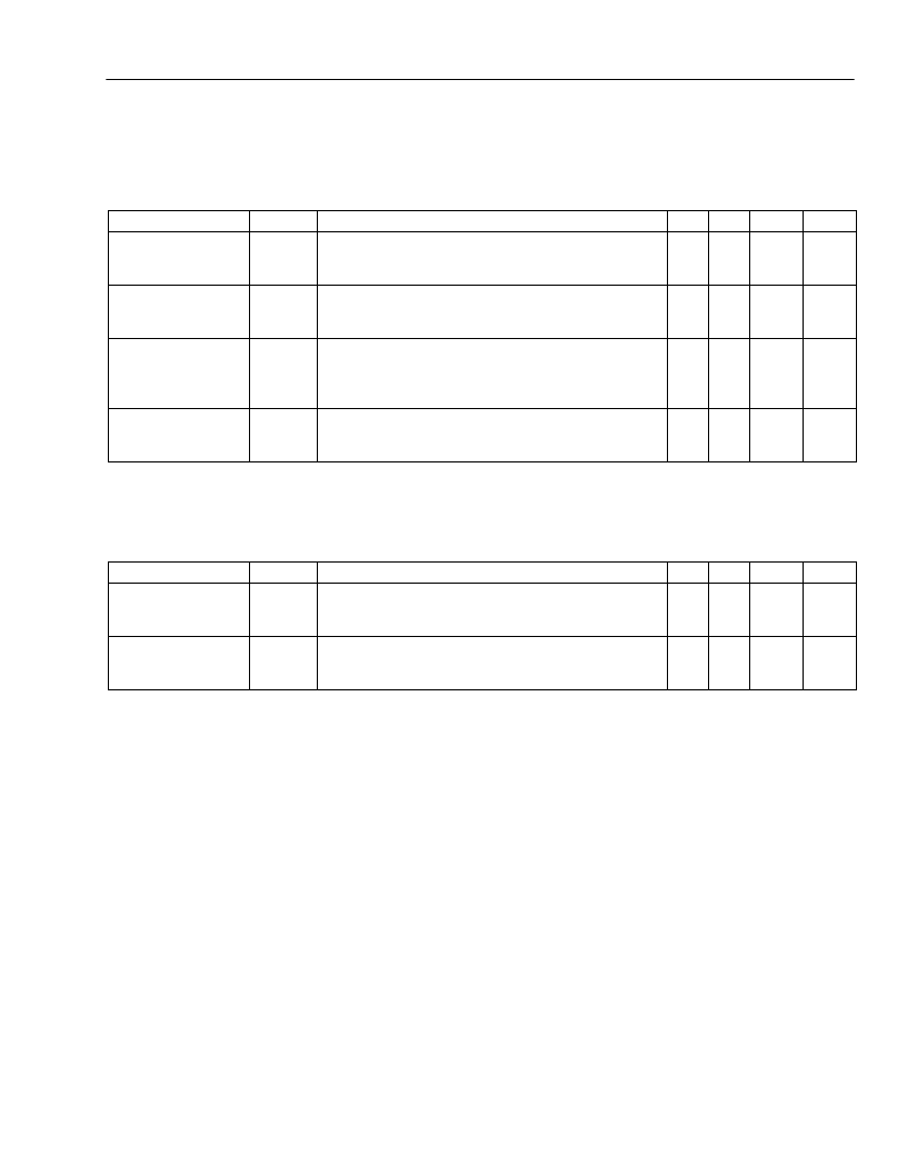
Table 12. Interchannel Crosstalk (Between Channels) R
F
=
≤
400 k
*
Parameter
Transmit to Receive
Crosstalk 0 dBm0
Transmit Levels
Receive to Transmit
Crosstalk 0 dBm0
Receive Levels
Transmit to Trans-
mit Crosstalk
0 dBm0 Transmit
Levels
Receive to Receive
Crosstalk 0 dBm0
Receive Levels
Symbol
CT
XX-RY
Test Conditions
f = 300 Hz—3400 Hz
idle PCM code for channel under test;
0 dBm0 into any other single-channel VF
X
IN
f = 300 Hz—3400 Hz
VF
X
IN = 0 Vrms for channel under test;
0 dBm0 code level on any other single-channel D
R
f = 300 Hz—3400 Hz
0 dBm0 applied to any single-channel
VF
X
IN except channel under test,
which has VF
X
IN = 0 Vrms
f = 300 Hz—3400 Hz
0 dBm0 code level on any single-channel D
R
except
channel under test which has idle code applied
Min
—
Typ
—
Max
–75
Unit
dB
CT
RX-XY
—
—
–75
dB
CT
XX-XY
—
—
–75
dB
CT
RX-RY
—
—
–75
dB
Table 13. Intrachannel Crosstalk (Within Channels) R
F
=
≤
400 k
*
Parameter
Transmit to Receive
Crosstalk 0 dBm0
Transmit Levels
Receive to Transmit
Crosstalk 0 dBm0
Receive Levels
Symbol
CT
XX-RX
Test Conditions
f = 300 Hz—3400 Hz
idle PCM code for channel under test;
0 dBm0 into VF
X
IN
f = 300 Hz—3400 Hz
VF
X
IN = 0 Vrms for channel under test;
0 dBm0 code level on D
R
Min
—
Typ
—
Max
–65
Unit
dB
CT
RX-XX
—
—
–65
dB
相關PDF資料 |
PDF描述 |
|---|---|
| T7504 | T7504 and T75504 Quad PCM Codecs with Filters |
| T7507 | T7507 Quad PCM Codec with Filters, Termination Impedance, and Hybrid Balance |
| T7570 | T7570 Programmable PCM Codec with Hybrid-Balance Filter |
| T7630 | T7630 Dual T1/E1 5.0 V Short-Haul Terminator (Terminator-II) |
| T7630 | Dual T1/E1 5.0 V Short-Haul Terminator (Terminator-II)(雙 T1/E1 5.0V短距離通信終端器) |
相關代理商/技術參數(shù) |
參數(shù)描述 |
|---|---|
| T75-03A | 制造商:The Cherry Corporation 功能描述: |
| T7504 | 制造商:AGERE 制造商全稱:AGERE 功能描述:T7504 and T75504 Quad PCM Codecs with Filters |
| T7507 | 制造商:AGERE 制造商全稱:AGERE 功能描述:T7507 Quad PCM Codec with Filters, Termination Impedance, and Hybrid Balance |
| T75-08M2 | 制造商:The Cherry Corporation 功能描述: |
| T-751 | 制造商:RHOMBUS-IND 制造商全稱:Rhombus Industries Inc. 功能描述:Fly Back Transformer |
發(fā)布緊急采購,3分鐘左右您將得到回復。