- 您現(xiàn)在的位置:買賣IC網(wǎng) > PDF目錄98183 > TC850IJL 1-CH 15-BIT MULTI-SLOPE ADC, PARALLEL ACCESS, CDIP40 PDF資料下載
參數(shù)資料
| 型號: | TC850IJL |
| 元件分類: | ADC |
| 英文描述: | 1-CH 15-BIT MULTI-SLOPE ADC, PARALLEL ACCESS, CDIP40 |
| 封裝: | CERDIP-40 |
| 文件頁數(shù): | 20/26頁 |
| 文件大?。?/td> | 417K |
| 代理商: | TC850IJL |
第1頁第2頁第3頁第4頁第5頁第6頁第7頁第8頁第9頁第10頁第11頁第12頁第13頁第14頁第15頁第16頁第17頁第18頁第19頁當(dāng)前第20頁第21頁第22頁第23頁第24頁第25頁第26頁

2006 Microchip Technology Inc.
DS21479C-page 3
TC850
1.0
ELECTRICAL SPECIFICATIONS
Absolute Maximum Ratings*
Positive Supply Voltage..........................................+6V
Negative Supply Voltage ....................................... - 9V
Analog Input Voltage (IN+ pr IN-) .............. VDD to VSS
Voltage Reference Input:
(REF1+, REF1–, REF2+).................. VDD to VSS
Logic Input Voltage............. VDD + 0.3V to GND – 0.3V
Current Into Any Pin...........................................10 mA
While Operating .....................................100
μA
Ambient Operating Temperature Range
C Device....................................... 0°C to +70°C
I Device......................................-25°C to +85°C
Package Power Dissipation (TA ≤ 70°C)
CerDIP .....................................................2.29
Ω
Plastic DIP................................................1.23
Ω
Plastic PLCC ...........................................1.23
Ω
*Stresses
above
those
listed
under
“Absolute
Maximum Ratings” may cause permanent damage to
the device. These are stress ratings only and functional
operation of the device at these or any other conditions
above those indicated in the operation sections of the
specifications is not implied. Exposure to Absolute
Maximum Rating conditions for extended periods may
affect device reliability.
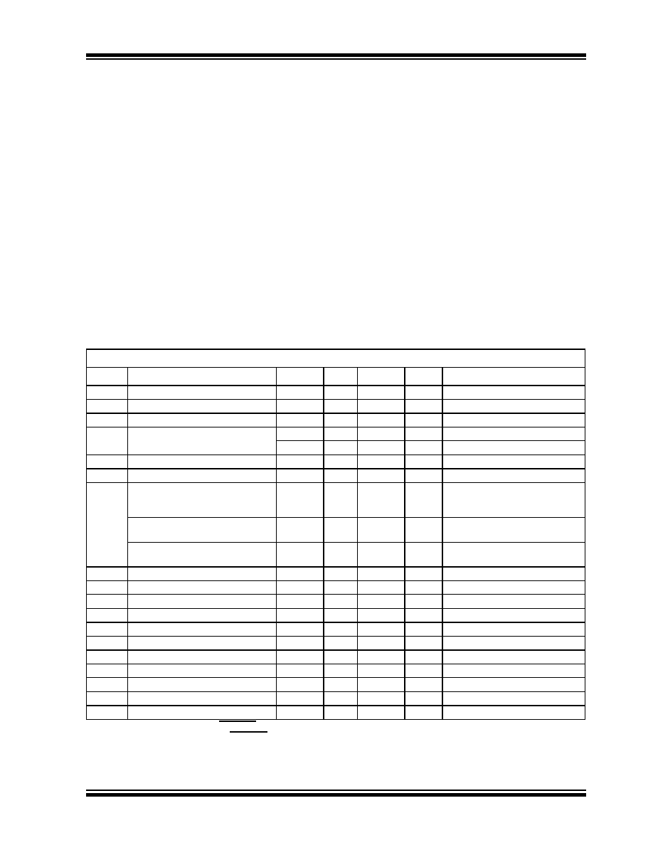
TABLE 1-1:
TC850 ELECTRICAL SPECIFICATIONS
Electrical Characteristics: VS = ±5V; FCLK = 61.44kHz, VFS = 3.2768V, TA = 25°C, Figure 1-1, unless otherwise specified.
Symbol
Parameter
Min
Typ
Max
Unit
Test Conditions
Zero Scale Error
±0.25
±0.5
LSB
VIN = 0V
End Point Linearity Error
—
±1
±2
LSB
-VFS ≤ VIN ≤ +VFS
Differential Nonlinearity
—
±0.1
±0.5
LSB
IIN
Input Leakage Current
—
30
75
pA
VIN = 0V, TA = 25°C
—
1.1
3
nA
-25°
≤ TA ≤ +85°C
VCMR
Common Mode Voltage Range
VSS + 1.5
—
VSS – 1.5
V
Over Operating Temperature Range
CMRR
Common Mode Rejection Ratio
—
80
—
dB
VIN = 0V, VCM = ±1V
Full Scale Gain Temperature
Coefficient
—
2
5
ppm/°C
External Ref. Temperature
Coefficient = 0 ppm/°C
0°C
≤ TA ≤ +70°C
Zero Scale Error
Temperature Coefficient
—
0.3
2
μV/°C V
IN = 0V
0°C
≤ TA ≤ +70°C
Full Scale Magnitude
Symmetry Error
—
0.5
2
LSB
VIN = ±3.275V
eN
Input Noise
—
30
—
μV
P-P
Not Exceeded 95% of Time
IS+
Positive Supply Current
—
2
3.5
mA
IS–
Negative Supply Current
—
2
3.5
mA
VOH
Output High Voltage
3.5
4.9
—
V
IO = 500 μA
VOL
Output Low Voltage
—
0.15
0.4
V
IO = 1.6 mA
IOP
Output Leakage Current
—
0.1
1
μA
Pins 8 -15, High-impedance State
VIH
Input High Voltage
3.5
2.3
—
V
VIL
Input Low Voltage
—
2.1
1
V
IPU
Input Pull-Up Current
—
4
—
μA
Pins 2, 3, 4, 6, 7; VIN = 0V
IPD
Input Pull-Down Current
—
14
—
μA
Pins 1, 5; VIN = 5V
IOSC
Oscillator Output Current
—
140
—
μA
Pin 18, VOUT = 2.5V
Note
1:
2: Continuous mode, CONT/DEMAND = HIGH. Figure 8-4 timing diagram.
3: Digital inputs have CMOS logic levels and internal pull-up/pull-down resistors. For TTL compatibility, external pull-up
resistors to VDD are recommended.
相關(guān)PDF資料 |
PDF描述 |
|---|---|
| TC850ILW713 | 1-CH 15-BIT MULTI-SLOPE ADC, PARALLEL ACCESS, PQCC44 |
| TC850ILWTR | 1-CH 15-BIT MULTI-SLOPE ADC, PARALLEL ACCESS, PQCC44 |
| TC850CLW | 1-CH 15-BIT MULTI-SLOPE ADC, PARALLEL ACCESS, PQCC44 |
| TC850CLWTR | 1-CH 15-BIT MULTI-SLOPE ADC, PARALLEL ACCESS, PQCC44 |
| TC850CLW713 | 1-CH 15-BIT MULTI-SLOPE ADC, PARALLEL ACCESS, PQCC44 |
相關(guān)代理商/技術(shù)參數(shù) |
參數(shù)描述 |
|---|---|
| TC850ILW | 功能描述:模數(shù)轉(zhuǎn)換器 - ADC 16 Bit Hi Speed A/D RoHS:否 制造商:Texas Instruments 通道數(shù)量:2 結(jié)構(gòu):Sigma-Delta 轉(zhuǎn)換速率:125 SPs to 8 KSPs 分辨率:24 bit 輸入類型:Differential 信噪比:107 dB 接口類型:SPI 工作電源電壓:1.7 V to 3.6 V, 2.7 V to 5.25 V 最大工作溫度:+ 85 C 安裝風(fēng)格:SMD/SMT 封裝 / 箱體:VQFN-32 |
| TC850ILW713 | 功能描述:模數(shù)轉(zhuǎn)換器 - ADC 16 Bit Hi Speed A/D RoHS:否 制造商:Texas Instruments 通道數(shù)量:2 結(jié)構(gòu):Sigma-Delta 轉(zhuǎn)換速率:125 SPs to 8 KSPs 分辨率:24 bit 輸入類型:Differential 信噪比:107 dB 接口類型:SPI 工作電源電壓:1.7 V to 3.6 V, 2.7 V to 5.25 V 最大工作溫度:+ 85 C 安裝風(fēng)格:SMD/SMT 封裝 / 箱體:VQFN-32 |
| TC8521AM | 制造商:TOSHIBA 制造商全稱:Toshiba Semiconductor 功能描述:REAL TIME CLOCK ケ |
| TC8521AP | 制造商:TOSHIBA 制造商全稱:Toshiba Semiconductor 功能描述:REAL TIME CLOCK ケ |
| TC8566AF | 制造商:TOSHIBA 制造商全稱:Toshiba Semiconductor 功能描述:FLOPPY DISK CONTROLLER |
發(fā)布緊急采購,3分鐘左右您將得到回復(fù)。