- 您現(xiàn)在的位置:買賣IC網(wǎng) > PDF目錄373606 > TC9325F (Toshiba Corporation) Single-Chip DTS Microcontroller (DTS-20) PDF資料下載
參數(shù)資料
| 型號: | TC9325F |
| 廠商: | Toshiba Corporation |
| 英文描述: | Single-Chip DTS Microcontroller (DTS-20) |
| 中文描述: | 單芯片微丘(丘- 20) |
| 文件頁數(shù): | 78/101頁 |
| 文件大?。?/td> | 1802K |
| 代理商: | TC9325F |
第1頁第2頁第3頁第4頁第5頁第6頁第7頁第8頁第9頁第10頁第11頁第12頁第13頁第14頁第15頁第16頁第17頁第18頁第19頁第20頁第21頁第22頁第23頁第24頁第25頁第26頁第27頁第28頁第29頁第30頁第31頁第32頁第33頁第34頁第35頁第36頁第37頁第38頁第39頁第40頁第41頁第42頁第43頁第44頁第45頁第46頁第47頁第48頁第49頁第50頁第51頁第52頁第53頁第54頁第55頁第56頁第57頁第58頁第59頁第60頁第61頁第62頁第63頁第64頁第65頁第66頁第67頁第68頁第69頁第70頁第71頁第72頁第73頁第74頁第75頁第76頁第77頁當前第78頁第79頁第80頁第81頁第82頁第83頁第84頁第85頁第86頁第87頁第88頁第89頁第90頁第91頁第92頁第93頁第94頁第95頁第96頁第97頁第98頁第99頁第100頁第101頁
TC9325F
2002-05-14
78
Setting mode
conditions
First set up the following operating conditions
●
SIO
on
=
1: Enables serial interface.
●
EDGE
=
0: Sets rising edge shift.
●
SCKO
=
1: Sets serial clock output (master mode).
●
SCK-INV
=
0: Sets positive logic output.
●
8BIT
=
1: Sets 8-bit operations.
●
Nch
=
1: Sets N-channel open drain output.
●
MSB
=
1: Sets input/output data from MSB
●
MOD
=
1: Sets 2-line serial interface operations.
●
CK0/1: Sets by operating frequency.
When outputting serial data, first set data to the serial output data port (
φ
L2CA,
φ
L2CB). If TC9325F is the
master, set SCKO
=
1; if the slave, set SCKO
=
0; if data output, set SO1
=
0; if data input, set SOI
=
1.
Start conditions
(Timing A)
If TC9325F is the master, control the start conditions output by software. If the slave, set to wait after setting
the start conditions.
For software control when TC9325F is the master, set the SO3/SO4 and SCK3/SCK4 bits to 1 to set software
control (ENA
=
1) (
φ
L14P3
←
FH). Set bits SO3/SO4 to 0 (
φ
L14P3
←
EH), then set the SCK3/SCK4 bits to 0
(
φ
L14P3
←
CH) to output the start condition waveform. At that time, the serial operation automatically starts
on the rising edge of the SCK4 pin, as when STA
=
1 is set (no need to set STA
=
1). If the serial data
input/output (SOI) setting has been changed, the serial data input/output (SOI) is updated on the serial clock
’
s
falling edge.
If TC9325F is set as a slave, shift operations start automatically at the start conditions.
Serial operations
(Timing B)
When serial operations start, the flags are set as follows:
BUSY
=
1: Serial operation in progress.
BUSY4
=
1: Set to 1 at start condition. 2-line serial operation in progress.
STA F/F
=
1: Set to 1 at start condition. Detects 2-line serial operation start signal.
SIO F/F
=
1: Set to 1 on SCK4 pin rising edge (1). Detects serial operation clock.
ENA
=
0: Serial operation input/output state.
In serial operations, the SO4 pin state is input to the serial interface on a rising edge; serial data are output on
a falling edge.
On the falling edges of the eight serial clocks, the following states are set automatically:
BUSY
=
0: Serial operations complete
BUSY4
=
1: Two-line serial operation in progress.
STA F/F: Flag held
SIO F/F: Flag held
ENA
=
1: Under software control (SO3/SO4, SCK3/SCK4 bits output)
SCK3/SCK4
=
0: SCK4 pin set to L and clock wait state set
In addition, a serial interface interrupt is generated if the interrupt is enabled.
When the TC9325F is the master, even though an H level (pulled-up state) is output to the SCK4 pin during a
serial operation, if the pin state is L (waiting for the clock from another device), the serial clock is halted until
the clock of the other device is released.
Even though an H level is output from the SDA pin during serial data output, if the pin state is L (simultaneous
output detected on a multi-master system), the SO3/SO4, SCK3/SCK4, and ENA bits are automatically set to
1 and software control is set on the SCL clock rising edge, then the output is released (Hz). At that time, the
SO-NG F/F bit is set to 1.
To output an H level from the SO3/SO4 pin after the serial operation completes (set to 0 on the start
condition), set the SO3/SO4 bit to 1 (
φ
L14P3
←
9H or 6H) during a serial operation.
Where the stop conditions are satisfied during a serial operation, an interrupt is generated if enabled.
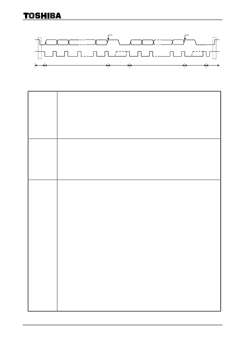
2-Line Serial Interface Timing Example
SCK4
pin
SO4
pin
Interrupt
Start condition
Stop condition
D7
D6
D5
D0
(ACK)
ACK
D7
D4
1
2
3
A
B
C
D1
7
8
(WAIT)
9
1
2
B
C
D
7
D1
D0
8
Interrupt
(ACK)
ACK
(WAIT)
9
相關PDF資料 |
PDF描述 |
|---|---|
| TC9327 | DTS MICROCONTROLLER |
| TC9327F | DTS MICROCONTROLLER |
| TC9331 | AUDIO DIGITAL SIGNAL PROCESSOR |
| TC9331F | AUDIO DIGITAL SIGNAL PROCESSOR |
| TC9332 | AUDIO DIGITAL SIGNAL PROCESSOR |
相關代理商/技術參數(shù) |
參數(shù)描述 |
|---|---|
| TC9327 | 制造商:TOSHIBA 制造商全稱:Toshiba Semiconductor 功能描述:DTS MICROCONTROLLER |
| TC9327BFG | 制造商:TOSHIBA 制造商全稱:Toshiba Semiconductor 功能描述:DTS Microcontroller (DTS-21) |
| TC9327F | 制造商:TOSHIBA 制造商全稱:Toshiba Semiconductor 功能描述:DTS MICROCONTROLLER |
| TC9328AF | 制造商:TOSHIBA 制造商全稱:Toshiba Semiconductor 功能描述:Portable Audio DTS Controller (DTS-21) |
| TC9328AF_04 | 制造商:TOSHIBA 制造商全稱:Toshiba Semiconductor 功能描述:Portable Audio DTS Controller (DTS-21) |
發(fā)布緊急采購,3分鐘左右您將得到回復。