- 您現(xiàn)在的位置:買賣IC網(wǎng) > PDF目錄373629 > TEA2028-TEA2029 (意法半導(dǎo)體) APPLICATION NOTE PDF資料下載
參數(shù)資料
| 型號(hào): | TEA2028-TEA2029 |
| 廠商: | 意法半導(dǎo)體 |
| 英文描述: | APPLICATION NOTE |
| 中文描述: | 應(yīng)用筆記 |
| 文件頁數(shù): | 21/47頁 |
| 文件大小: | 532K |
| 代理商: | TEA2028-TEA2029 |
第1頁第2頁第3頁第4頁第5頁第6頁第7頁第8頁第9頁第10頁第11頁第12頁第13頁第14頁第15頁第16頁第17頁第18頁第19頁第20頁當(dāng)前第21頁第22頁第23頁第24頁第25頁第26頁第27頁第28頁第29頁第30頁第31頁第32頁第33頁第34頁第35頁第36頁第37頁第38頁第39頁第40頁第41頁第42頁第43頁第44頁第45頁第46頁第47頁
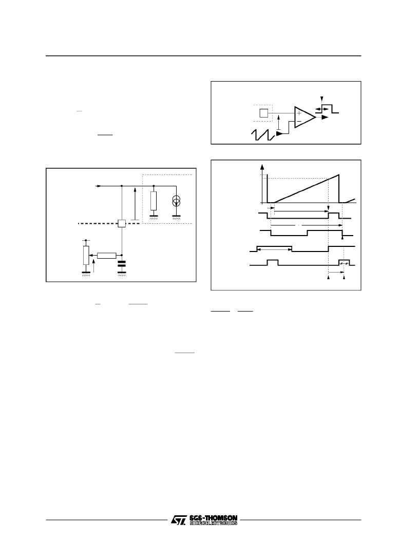
V.5.2.2- Low-pass filter f(p)
The horizontalphase-shift adjustmentis takeninto
account: see Figure39
- FilterV = f(i) transfer characteristicis given as :
V = Zi +Z
R
K
V
CC
- Z
I
IN
Where :
Z = R
IN
// R//
C
p
R
IN
, I
IN
: modulator input characteristics
1
16
R
IN
I
IN
Phase Modulator
V
V
CC
+
C
P
KV
CC
Horizontal
Phase
Adjust
R
i
2
Comparator
2
Figure39
In Dynamic Mode
- V = Zi
f(p) =V
i= Z(p) =
R
′
1
+ τ
p
Where:
R’= R
IN
// R (R >> PotentiometerP)
τ
= R’ . C : Filter time constant
The networkbehavesasafirst orderlow-pass filter
whose cut-off frequencyat -3dBis : f
-3dB
=
1
2
π
R
′
C
Filter component values
- R = 470k
and C = 22nF
In practice, (K
∈
[0,1])V
CC
= 12V
- R
IN
= 25M
, I
IN
= 0.65
μ
A(base input current)
F
3db
= 15.7Hz with adjustmentand0.3Hz with-
out adjustment
V.5.2.3 - Phasemodulator
This is built around a comparator which converts
the filter voltage to a rectangular waveform such
that its rising edgephase, variable as afunction of
filter voltage ”V”, will trigger theline transistor turn-
off controlcircuitry.
The conversiongain is determined by the slope of
the line saw-toothappliedto comparator.
16
t’
OUT
V’
OUT
V
V
13
(t)
2
Figure 40
V
13
(t)
t
1
= f(v)
t
2
V’
OUT
V
2
t
D
t’
OUT
t
OUT
= 0
t
IN
3.5V
0
Line Output
Signal (Pin 10)
Line Flyback
(LF)
V
t
IN(
2)
T
H
T
10
= constant
2
Figure 41
Transfer characteristic is given by :
t
′
OUT
V
Let’s consider the delay interval between ”t
OUT
”
and the referencetime ”t
IN
”
where t
OUT
is the middle of line flyback :
t
OUT
- t
IN
= t
2
+ t
d
+ t
1
- t
H
Where :
- t1 = 4.3
μ
s
ResetforV
13
andV
φ2
aresignalscomingfromline
logicblock and are synchronizedon line sync
- t
d
= 2 to 15
μ
s
Delay between leading edge of output signal -
Pin 10 - and the middle of line flyback
- t
H
= 64
μ
s
- t
OUT
- t
IN
= B.V + t
d
- 59.7
μ
s
=
t
13
V
13
= B = 16.4
μ
s/V thereforet
2
= B.V
V.5.2.4-Lineflip-flop
(TEA2028onlyforTEA2029
refer to Section VII.6)
It generatesa constantdurationrectangularsignal
used to turn-offthe line transistor. Itis triggeredby
the rising-edge of the phase comparator output
voltage and reset after capacitor on pin 1 is
charged.
TEA2028 - TEA2029 APPLICATIONNOTE
21/46
相關(guān)PDF資料 |
PDF描述 |
|---|---|
| TEA2028 | APPLICATION NOTE |
| TEA2028B | SWITCH MODE POWER SUPPLY PRIMARY CIRCUIT |
| TEA2128 | SWITCH MODE POWER SUPPLY PRIMARY CIRCUIT |
| TEA2164S | SWITCH MODE POWER SUPPLY PRIMARY CIRCUIT |
| TEA2029C | COLOR TV SCANNING AND POWER SUPPLY PROCESSOR |
相關(guān)代理商/技術(shù)參數(shù) |
參數(shù)描述 |
|---|---|
| TEA2029 | 制造商:STMICROELECTRONICS 制造商全稱:STMicroelectronics 功能描述:APPLICATION NOTE |
| TEA2029C | 制造商:STMICROELECTRONICS 制造商全稱:STMicroelectronics 功能描述:COLOR TV SCANNING AND POWER SUPPLY PROCESSOR |
| TEA2029CV | 制造商:TEMIC 制造商全稱:TEMIC Semiconductors 功能描述:Timing Processor (LINE, FRAME, SMPS) for TV Sets |
| TEA2031A | 功能描述:視頻 IC East/West Correction RoHS:否 制造商:Fairchild Semiconductor 工作電源電壓:5 V 電源電流:80 mA 最大工作溫度:+ 85 C 封裝 / 箱體:TSSOP-28 封裝:Reel |
| TEA2031A_07 | 制造商:STMICROELECTRONICS 制造商全稱:STMicroelectronics 功能描述:COLOR TV EAST-WEST CORRECTION |
發(fā)布緊急采購(gòu),3分鐘左右您將得到回復(fù)。