- 您現(xiàn)在的位置:買(mǎi)賣(mài)IC網(wǎng) > PDF目錄373629 > TEA2028 (意法半導(dǎo)體) APPLICATION NOTE PDF資料下載
參數(shù)資料
| 型號(hào): | TEA2028 |
| 廠商: | 意法半導(dǎo)體 |
| 英文描述: | APPLICATION NOTE |
| 中文描述: | 應(yīng)用筆記 |
| 文件頁(yè)數(shù): | 23/47頁(yè) |
| 文件大小: | 532K |
| 代理商: | TEA2028 |
第1頁(yè)第2頁(yè)第3頁(yè)第4頁(yè)第5頁(yè)第6頁(yè)第7頁(yè)第8頁(yè)第9頁(yè)第10頁(yè)第11頁(yè)第12頁(yè)第13頁(yè)第14頁(yè)第15頁(yè)第16頁(yè)第17頁(yè)第18頁(yè)第19頁(yè)第20頁(yè)第21頁(yè)第22頁(yè)當(dāng)前第23頁(yè)第24頁(yè)第25頁(yè)第26頁(yè)第27頁(yè)第28頁(yè)第29頁(yè)第30頁(yè)第31頁(yè)第32頁(yè)第33頁(yè)第34頁(yè)第35頁(yè)第36頁(yè)第37頁(yè)第38頁(yè)第39頁(yè)第40頁(yè)第41頁(yè)第42頁(yè)第43頁(yè)第44頁(yè)第45頁(yè)第46頁(yè)第47頁(yè)
Open-collector output:
V
10(SAT)
< 1.5V at I
10(MAX)
= 20mA
The line output (Pin 10) will go high if either the
followingthree inhibitionsis activated :
A. INHIBITIONAT START-UP
Thisisgeneratedbyahysteresiscomparatorwhich
is driven by ”KV
CC
” and the ”1.26V” reference
voltage.
This inhibition is mandatory since the device will
operate only at V
CC
≥
5V.
V
HYST
= 0.5V
1
0
5.5 6
SUPPLY VOLTAGE(V)
L
(
2
Figure45
B. INHIBITIONDURING LINE FLYBACK
The outputsignalPin 10 is highduringline transis-
tor turn-off. The leading edge of output signal
Pin 10 turns off the line transistor after a delay
interval(storage time).
The line transistor turn-off generates an overvol-
tage on the collector corresponding to the line
flyback pulse. During this interval,in orderto avoid
transistor destruction, the Pin 10 output must ab-
solutely remainhigh.
This is done internally with the line flyback pulse
(Pin 12), which forces Pin 10 output to high level
during the line flyback time.
C. SAFETYINHIBITION
The device has a security input terminal ”P(pán)in 28”.
If asignal lowerthanV
REF
(1.26V)isapplied to this
pin, line andpowersupply outputsareall inhibited.
This function is particularly useful for TV chassis
protection.Refer to sectionV.7.5forfurtherdetails.
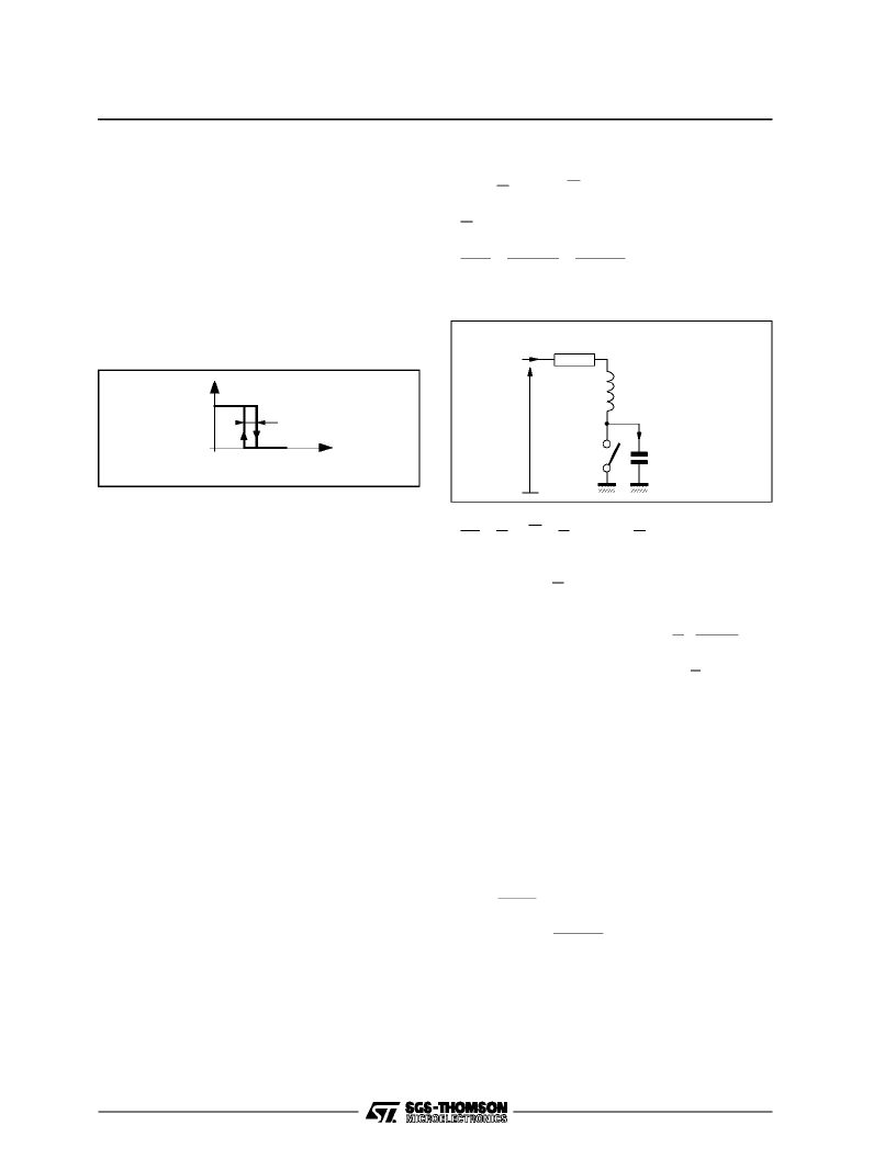
V.5.2.6 - Line deflectionstage
This chapterwill cover a generaldescription of the
”horizontal deflection stage” employed almost
commonlyin all recent TV sets.
Deflection of electron beam is proportional to the
intensityof magnetic fieldinducedbythe lineyoke.
This yoke is equivalent to an inductor.The deflec-
tion is thereforeproportional to thecurrent through
inductor.
In ordertoobtainalineardeflectionfromleftto right
as a function of time,a saw-toothcurrent must be
generatedwithintheyoke.The approachistoapply
a switchedDC voltage to the line yoke.
- When K is closed :
i
L(t)
=E
r
y
-L
r
y
is always higher than half of trace time :
t
trace
2
2
- ”i
L
” variationsas a functionof time :
Figure 46
1
e
ryt
L
=T
H
t
LF
=64
12
2
= 26
μ
s
C
K
E
i
L(t)
r
y
Deflection Yoke Resistance
Deflection Yoke
Inductance (L)
2
di
L
dt=E
The current will therefore be linear as a function
of time i
L(t)
=E
L
t from ”t
1
” to ”t
2
” which is the
secondportion of the line trace interval.
- Currentat the end of trace : I
M
=E
Le
ryt
L
≈
E
L
for
t
<
<
L
r
y
L
t
TRACE
2
L
I
M2
2
- Energy stored within inductor: W=1
If the switch is opened at t = t
2
, the ”L.C” combi-
nationwillenterinto oscillation,theenergystored
within inductor is transfered to the capacitor,
which will returnit to the inductorand so on.
The circuit period is classically given by :
T = 2
π
√
If ”K” is closed at time ”t
3
”, the inductor will once
again have a voltage ”E” across its terminals. The
current falls linearly until ”t
4
”. This phase corre-
spondsto the first half of line trace interval.
The overvoltageacross C is:
V
P
= Et
trace
2
√
That is : V
P
= Et
trace
π
2t
LF
In practice, E is higher than 100V.
t
trace
= 52
μ
s, t
LF
= 12
μ
s
V
P
≥
780V
Note that this overvoltageis almost 8 times higher
than the source voltage ”E”. This overvoltage is
appliedto the primary winding of a ”step-up trans-
former” (EHTTransformer)inordertogeneratethe
high voltage required by picture tube anode.
LF
≈
π
√
+ E
TEA2028 - TEA2029 APPLICATIONNOTE
23/46
相關(guān)PDF資料 |
PDF描述 |
|---|---|
| TEA2028B | SWITCH MODE POWER SUPPLY PRIMARY CIRCUIT |
| TEA2128 | SWITCH MODE POWER SUPPLY PRIMARY CIRCUIT |
| TEA2164S | SWITCH MODE POWER SUPPLY PRIMARY CIRCUIT |
| TEA2029C | COLOR TV SCANNING AND POWER SUPPLY PROCESSOR |
| TEA2031A | COLOR TV EAST-WEST CORRECTION |
相關(guān)代理商/技術(shù)參數(shù) |
參數(shù)描述 |
|---|---|
| TEA2028B | 制造商:STMICROELECTRONICS 制造商全稱(chēng):STMicroelectronics 功能描述:COLOR TV SCANNING AND POWER SUPPLY PROCESSOR |
| TEA2028-TEA2029 | 制造商:STMICROELECTRONICS 制造商全稱(chēng):STMicroelectronics 功能描述:APPLICATION NOTE |
| TEA2029 | 制造商:STMICROELECTRONICS 制造商全稱(chēng):STMicroelectronics 功能描述:APPLICATION NOTE |
| TEA2029C | 制造商:STMICROELECTRONICS 制造商全稱(chēng):STMicroelectronics 功能描述:COLOR TV SCANNING AND POWER SUPPLY PROCESSOR |
| TEA2029CV | 制造商:TEMIC 制造商全稱(chēng):TEMIC Semiconductors 功能描述:Timing Processor (LINE, FRAME, SMPS) for TV Sets |
發(fā)布緊急采購(gòu),3分鐘左右您將得到回復(fù)。