- 您現(xiàn)在的位置:買賣IC網(wǎng) > PDF目錄373629 > TEA2028 (意法半導(dǎo)體) APPLICATION NOTE PDF資料下載
參數(shù)資料
| 型號(hào): | TEA2028 |
| 廠商: | 意法半導(dǎo)體 |
| 英文描述: | APPLICATION NOTE |
| 中文描述: | 應(yīng)用筆記 |
| 文件頁數(shù): | 43/47頁 |
| 文件大小: | 532K |
| 代理商: | TEA2028 |
第1頁第2頁第3頁第4頁第5頁第6頁第7頁第8頁第9頁第10頁第11頁第12頁第13頁第14頁第15頁第16頁第17頁第18頁第19頁第20頁第21頁第22頁第23頁第24頁第25頁第26頁第27頁第28頁第29頁第30頁第31頁第32頁第33頁第34頁第35頁第36頁第37頁第38頁第39頁第40頁第41頁第42頁當(dāng)前第43頁第44頁第45頁第46頁第47頁
The biasvoltage”V
B
” is suppliedby the secondary
winding of EHTtransformer. Theparaboliceffectis
due to the integration of frame saw-tooth by the
filtering capacitor ”C1”.
DVB =I
Y
T
8
C1= 0.95V
Where :
- I
Y
: Peak-to-peakyoke current = 380mA
pp
- T : 20ms
- C1 = 1000
μ
F
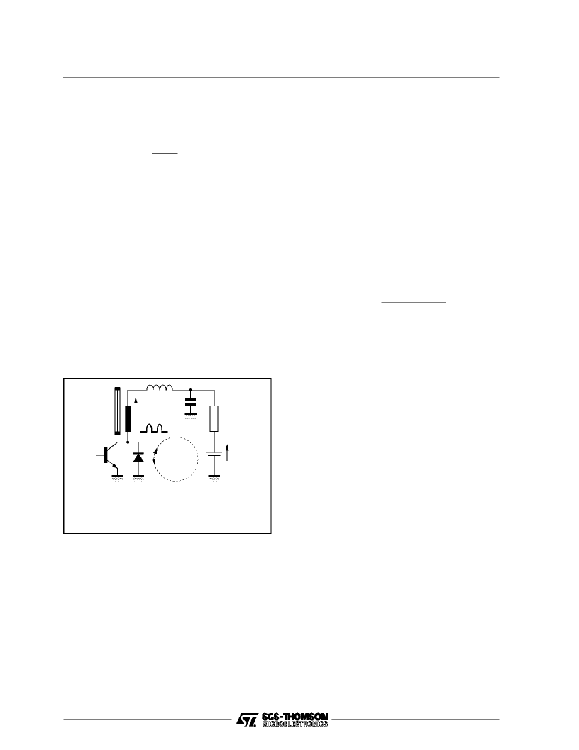
VIII.5- FrameFlyback
During flyback, due to the loop time constant, the
frame yoke current cannot be locked onto the
reference saw-tooth. Thus the output of amplifier
”A” will remain high and the thyristoris blocked.
The scanning current will begin flowing through
diode ”D”. As a consequence, the capacitor ”C”
startscharginguptotheflybackvoltage.Thethyris-
toristriggeredassoonastheyoke currentreaches
the maximum positive value.
EHTtransformerwinding (see Figure 88)
(for 90
o
tube : Yoke
L= 120mH, r
Y
= 60
)
VIII.6 - Feed-back Circuit
VIII.6.1 - Frame power in quasi-bridge configu-
ration
(see Figure 89)
This stagemeasurestheframe scanningcurrentin
differentialmode and compares it to the reference
saw-tooth on Pin 3.
The overall configuration is built around two sym-
metrical networks :
- ”R
1
, R
2
, R
3
” network : determines the dynamic
saw-tooth voltage
- ”R’
1
, R’
2
, R’
3
” network: setsthe bias voltageand
the d.c. shift control.
A.C.gain : G =R
2
V
IN
α
R
M
where :
- I
Y
: Peak-to-peakYoke Current
- V
IN
: Peak-to-peaksaw-toothvoltage (Pin 3)
-
α
∈
[0,1]: amplitudeadjustment
R
1
=I
Y
VIII.6.1.1- Choice of ”R” value
The saw-tooth generator output is an emitter fol-
lower stage. Pin3 outputcurrent must thereforebe
always negative.
R <<R1
V
IN
(
Min.
)
V
BIAS
V
IN
(
Min.
)
Where :
- V
BIAS
: Bias voltagefor Pins1 and2
- V
IN(MIN)
: Saw-toothvoltage low level
Example:
- R1 = 22k
- V
BIAS
= 5V
- V
IN(Min.)
= 1.26V
R
≈
R
1
10
VIII.6.1.2- Influence of R3 value
R
3
sets the bias voltage for Pins 1 and 2. This
voltage shouldbe lower than 5.5V so as to enable
the frame to function upon initial start-up at
V
CC
= 6V.
If the bias voltageishigher than this5.5Vlevel, the
d.c. open-loop gain will fall thereby rendering the
system more sensitiveto d.c. drift.
Satisfactory results are obtained at V
BIAS
values
falling within 4V to 5V range.
R3 = R2
V
BIAS
V
B
[V
IN
(
MEAN
)
G]
V
BIAS
[1
G]
Where : V
IN(MEAN
) : saw-tooth mean value (Pin 3)
Capacitor ”C” connected between Pins 1 and 2
determinesthe system stability. Its value must be
appropriately calculated as a function of ”R
1
, R
2
and R
3
” values so as to reject the line frequency
component.
V
LF
C
V
B
Load
Yoke
I
I
DIODE
THYRISTOR
L
2
-
V
LF
= 210V
PP
-
I
YOKE
= 380mA
PP
-
L= 500
μ
H
-
C = 0.47
μ
F
-
V
LF
≈
9.2 I
Y(PP)
r
Y
-
Flyback duration = 1ms
Figure88
TEA2028 - TEA2029 APPLICATIONNOTE
43/46
相關(guān)PDF資料 |
PDF描述 |
|---|---|
| TEA2028B | SWITCH MODE POWER SUPPLY PRIMARY CIRCUIT |
| TEA2128 | SWITCH MODE POWER SUPPLY PRIMARY CIRCUIT |
| TEA2164S | SWITCH MODE POWER SUPPLY PRIMARY CIRCUIT |
| TEA2029C | COLOR TV SCANNING AND POWER SUPPLY PROCESSOR |
| TEA2031A | COLOR TV EAST-WEST CORRECTION |
相關(guān)代理商/技術(shù)參數(shù) |
參數(shù)描述 |
|---|---|
| TEA2028B | 制造商:STMICROELECTRONICS 制造商全稱:STMicroelectronics 功能描述:COLOR TV SCANNING AND POWER SUPPLY PROCESSOR |
| TEA2028-TEA2029 | 制造商:STMICROELECTRONICS 制造商全稱:STMicroelectronics 功能描述:APPLICATION NOTE |
| TEA2029 | 制造商:STMICROELECTRONICS 制造商全稱:STMicroelectronics 功能描述:APPLICATION NOTE |
| TEA2029C | 制造商:STMICROELECTRONICS 制造商全稱:STMicroelectronics 功能描述:COLOR TV SCANNING AND POWER SUPPLY PROCESSOR |
| TEA2029CV | 制造商:TEMIC 制造商全稱:TEMIC Semiconductors 功能描述:Timing Processor (LINE, FRAME, SMPS) for TV Sets |
發(fā)布緊急采購,3分鐘左右您將得到回復(fù)。