- 您現(xiàn)在的位置:買賣IC網(wǎng) > PDF目錄98253 > TLV320AIC27TPFB (TEXAS INSTRUMENTS INC) SPECIALTY CONSUMER CIRCUIT, PQFP48 PDF資料下載
參數(shù)資料
| 型號(hào): | TLV320AIC27TPFB |
| 廠商: | TEXAS INSTRUMENTS INC |
| 元件分類: | 消費(fèi)家電 |
| 英文描述: | SPECIALTY CONSUMER CIRCUIT, PQFP48 |
| 封裝: | PLASTIC, TQFP-48 |
| 文件頁(yè)數(shù): | 14/54頁(yè) |
| 文件大小: | 732K |
| 代理商: | TLV320AIC27TPFB |
第1頁(yè)第2頁(yè)第3頁(yè)第4頁(yè)第5頁(yè)第6頁(yè)第7頁(yè)第8頁(yè)第9頁(yè)第10頁(yè)第11頁(yè)第12頁(yè)第13頁(yè)當(dāng)前第14頁(yè)第15頁(yè)第16頁(yè)第17頁(yè)第18頁(yè)第19頁(yè)第20頁(yè)第21頁(yè)第22頁(yè)第23頁(yè)第24頁(yè)第25頁(yè)第26頁(yè)第27頁(yè)第28頁(yè)第29頁(yè)第30頁(yè)第31頁(yè)第32頁(yè)第33頁(yè)第34頁(yè)第35頁(yè)第36頁(yè)第37頁(yè)第38頁(yè)第39頁(yè)第40頁(yè)第41頁(yè)第42頁(yè)第43頁(yè)第44頁(yè)第45頁(yè)第46頁(yè)第47頁(yè)第48頁(yè)第49頁(yè)第50頁(yè)第51頁(yè)第52頁(yè)第53頁(yè)第54頁(yè)

TLV320AIC27
STEREO AUDIO CODEC
SLAS253A – MARCH 2000 – REVISED SEPTEMBER 2000
21
POST OFFICE BOX 655303
DALLAS, TEXAS 75265
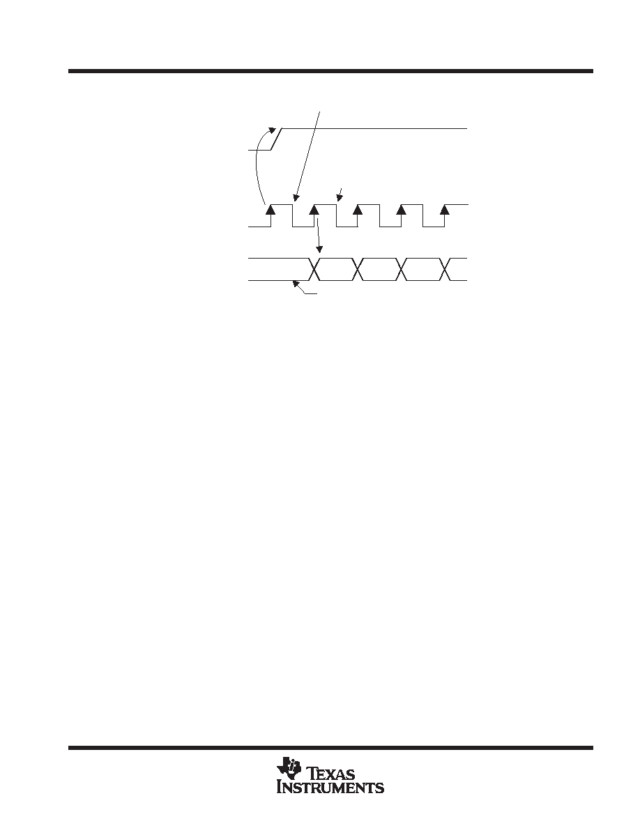
ac-link audio output frame (SDATA_OUT) (continued)
SYNC
BIT_CLK
SDATA_OUT
VALID
FRAME
SLOT (1)
SLOT (2)
SYNC ASSERTION HERE
AIC27 SAMPLES
FIRST SDATA_OUT
BIT OF FRAME HERE
END OF PREVIOUS AUDIO FRAME
AIC27 SAMPLES
Figure 10. Start of an Audio Output Frame
A new audio output frame begins with a low-to-high transition of SYNC, as shown in Figure 10. SYNC is
synchronized to the rising edge of BIT_CLK. On the falling edge of BIT_CLK immediately following, the
TLV320AIC27 samples the assertion of SYNC. This falling edge marks the time when both sides of the ac link
are aware of the start of a new audio frame. On the next rising edge of BIT_CLK, AC’97 transitions SDATA_OUT
into the first bit position of slot 0 (valid frame bit). Each new bit position is presented to the ac link on a rising
edge of BIT_CLK, and subsequently sampled by the TLV320AIC27 on the following falling edge of BIT_CLK.
This sequence ensures that data transitions and subsequent sample points for both incoming and outgoing data
streams are time-aligned.
Baseline AC’97-specified audio functionality should always convert the sample rate to and from a fixed 48 ksps
on the AC’97 controller. This requirement ensures that interoperability between the AC’97 controller and the
TLV320AIC27, among other things, can be assured by definition for baseline specified AC’97 features.
SDATA_OUT’s composite stream is MSB justified (MSB first), with all invalid slot bit positions stuffed with 0s
by the AC’97 controller. In the event that there are less than 20 valid bits within an assigned and valid time slot,
the AC’97 controller always stuffs all trailing invalid bit positions of the 20-bit slot with 0s.
As an example, consider an eight-bit sample stream that is being played out to one of the TLV320AIC27’s DACs.
The first eight-bit positions are presented to the DAC (MSB justified), followed by the next 12-bit positions, which
are stuffed with 0s by the AC’97 controller. This ensures that, regardless of the resolution of the implemented
DAC (16, 18, or 20-bit), no dc biasing is introduced by the least significant bits. When mono audio sample
streams are outputted from the AC’97 controller, it is necessary that
both left and right sample-stream time slots
be filled with the same data.
slot 1: command address port
The command port is used to control features and monitor status for the TLV320AIC27 functions including, but
not limited to, mixer settings and power management (refer to the serial interface register map). The control
interface architecture supports up to 64 16-bit read/write registers, addressable on even-byte boundaries. Only
the even registers (00h, 02h, etc.) are valid. Access to odd registers (01h, 03h, etc.) is discouraged (if supported,
they should default to the preceding even-byte boundary—that is, a read from 01h returns the 16-bit contents
of 00h). The TLV320AIC27’s control register file is nonetheless readable as well as writeable to provide more
robust testability.
Audio output frame slot 1 communicates control register address and read/write command information to the
TLV320AIC27.
相關(guān)PDF資料 |
PDF描述 |
|---|---|
| TLV320AIC28IRGZR | SPECIALTY CONSUMER CIRCUIT, PQCC48 |
| TLV320AIC28IRGZ | SPECIALTY CONSUMER CIRCUIT, PQCC48 |
| TLV320AIC28IRGZRG4 | SPECIALTY CONSUMER CIRCUIT, PQCC48 |
| TLV320AIC28RGZR | SPECIALTY CONSUMER CIRCUIT, PQCC48 |
| TLV320AIC28RGZ | SPECIALTY CONSUMER CIRCUIT, PQCC48 |
相關(guān)代理商/技術(shù)參數(shù) |
參數(shù)描述 |
|---|---|
| TLV320AIC28 | 制造商:TI 制造商全稱:Texas Instruments 功能描述:STEREO AUDIO CODEC WITH INTERGRATED HEADPHONE AND SPEAKER AMPLIFIERS |
| TLV320AIC28_08 | 制造商:TI 制造商全稱:Texas Instruments 功能描述:STEREO AUDIO CODEC WITH INTEGRATED HEADPHONE AND SPEAKER AMPLIFIERS |
| TLV320AIC28EVM | 功能描述:音頻 IC 開(kāi)發(fā)工具 TLV320AIC28 Eval Mod RoHS:否 制造商:Texas Instruments 產(chǎn)品:Evaluation Kits 類型:Audio Amplifiers 工具用于評(píng)估:TAS5614L 工作電源電壓:12 V to 38 V |
| TLV320AIC28IRGZ | 功能描述:接口—CODEC Lo-Pwr Stereo Codec RoHS:否 制造商:Texas Instruments 類型: 分辨率: 轉(zhuǎn)換速率:48 kSPs 接口類型:I2C ADC 數(shù)量:2 DAC 數(shù)量:4 工作電源電壓:1.8 V, 2.1 V, 2.3 V to 5.5 V 最大工作溫度:+ 85 C 安裝風(fēng)格:SMD/SMT 封裝 / 箱體:DSBGA-81 封裝:Reel |
| TLV320AIC28IRGZG4 | 功能描述:接口—CODEC Lo-Pwr Stereo Codec RoHS:否 制造商:Texas Instruments 類型: 分辨率: 轉(zhuǎn)換速率:48 kSPs 接口類型:I2C ADC 數(shù)量:2 DAC 數(shù)量:4 工作電源電壓:1.8 V, 2.1 V, 2.3 V to 5.5 V 最大工作溫度:+ 85 C 安裝風(fēng)格:SMD/SMT 封裝 / 箱體:DSBGA-81 封裝:Reel |
發(fā)布緊急采購(gòu),3分鐘左右您將得到回復(fù)。