- 您現(xiàn)在的位置:買賣IC網(wǎng) > PDF目錄385942 > TNETA1545 (Texas Instruments, Inc.) Dual Differential PSEUDO-ECL to ECL Transistors and Dual Differential ECL to PSEUDO-ECL Transistors(雙差分ECL TO PSEUDO-ECL轉(zhuǎn)換器和ECL-PSEUDO TO ECL轉(zhuǎn)換器) PDF資料下載
參數(shù)資料
| 型號: | TNETA1545 |
| 廠商: | Texas Instruments, Inc. |
| 英文描述: | Dual Differential PSEUDO-ECL to ECL Transistors and Dual Differential ECL to PSEUDO-ECL Transistors(雙差分ECL TO PSEUDO-ECL轉(zhuǎn)換器和ECL-PSEUDO TO ECL轉(zhuǎn)換器) |
| 中文描述: | 雙差分偽ECL的ECL晶體管和雙差動ECL的偽ECL晶體管(雙差分ECL的偽- ECL轉(zhuǎn)換器和電化學發(fā)光偽的ECL轉(zhuǎn)換器) |
| 文件頁數(shù): | 2/4頁 |
| 文件大?。?/td> | 77K |
| 代理商: | TNETA1545 |
TNETA1545
DUAL DIFFERENTIAL PSEUDO-ECL TO ECL TRANSLATORS AND
DUAL DIFFERENTIAL ECL TO PSEUDO-ECL TRANSLATORS
SDNS005B – SEPTEMBER 1993 – REVISED OCTOBER 1995
2
POST OFFICE BOX 655303
DALLAS, TEXAS 75265
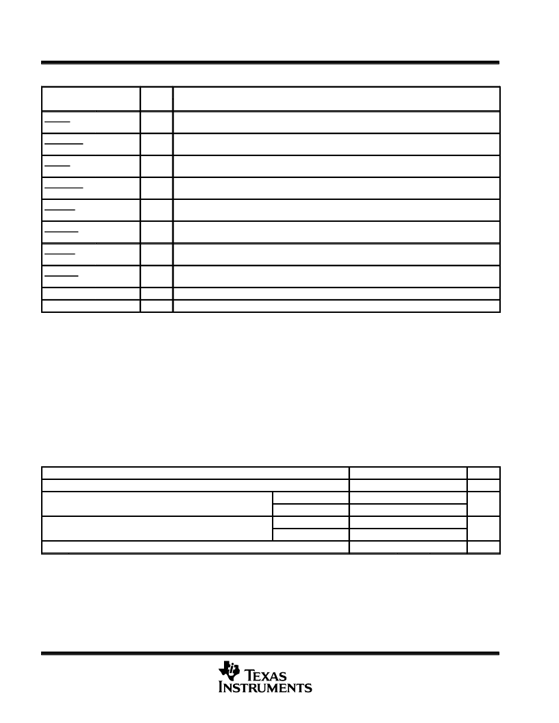
Terminal Functions
TERMINAL
I/O
DESCRIPTION
NAME
NO.
ECLIN1,
ECLIN1
3,
2
I
ECL-compatible inputs for ECL-to-PECL translator
PECLOUT1,
PECLOUT1
23,
22
O
PECL-compatible outputs from ECL-to-PECL translator
ECLIN2,
ECLIN2
6,
5
I
ECL-compatible intpus for ECL-to-PECL translator
PECLOUT2,
PECLOUT2
20,
19
O
PECL-compatible otuputs from ECL-to-PECL translator
PECLIN1,
PECLIN1
17,
16
I
PECL-compatible inputs fro PECL-to-ECL translator
ECLOUT1,
ECLOUT1
8,
9
O
ECL-compatible outputs from PECL-to-ECL translator
PECLIN2,
PECLIN2
15,
14
I
PECL-compatible inputs for PECL-to-ECL translator
ECLOUT2,
ECLOUT2
10,
11
O
ECL-compatible outputs from PECL-to-ECL translator
GND
7,12,13,18
Ground (0-V reference)
VCC
1,4,21,24
Supply voltage
absolute maximum rating over operating free-air temperature range (unless otherwise noted)
Supply voltage range, V
CC
(see Note 1)
Input voltage range: ECL
PECL
Operating free-air temperature range, T
A
Storage temperature range, T
stg
Stresses beyond those listed under “absolute maximum ratings” may cause permanent damage to the device. These are stress ratings only and
functional operation of the device at these or any other conditions beyond those indicated under “recommended operating conditions” is not
implied. Exposure to absolute-maximum-rated conditions for extended periods may affect device reliability.
NOTE 1: All voltage values are with respect to GND.
–0.5 V to 7 V
–2.5 V to 0 V
0 V to 7 V
–40
°
C to 85
°
C
–65
°
C to 150
°
C
. . . . . . . . . . . . . . . . . . . . . . . . . . . . . . . . . . . . . . . . . . . . . .
. . . . . . . . . . . . . . . . . . . . . . . . . . . . . . . . . . . . . . . . . . . . . . . . . . . . . . . . . . .
. . . . . . . . . . . . . . . . . . . . . . . . . . . . . . . . . . . . . . . . . . . . . . . . . . . . . . . . . . . . . .
. . . . . . . . . . . . . . . . . . . . . . . . . . . . . . . . . . . . . . . . . . .
. . . . . . . . . . . . . . . . . . . . . . . . . . . . . . . . . . . . . . . . . . . . . . . . . .
recommended operating conditions
MIN
NOM
MAX
UNIT
VCC
Supply voltage
4.75
5
5.25
V
VIH
High-level input voltage
ECL (see Note 2)
–1.165
–0.88
V
PECL (see Note 2)
VCC–1.165
–1.81
VCC–0.88
–1.475
VIL
Low-level input voltage
ECL (see Note 2)
V
PECL (see Note 2)
VCC–1.81
–40
VCC–1.475
TA
NOTE 2. The algebraic convention, in which the least positive (most negative) value is designated minimum, is used in this data sheet for
logic-level voltages only.
Operating free-air temperature
85
°
C
相關PDF資料 |
PDF描述 |
|---|---|
| TNETA1555 | 155.52-Mbit/S Clock-Recovery Device(155.52-MBIT/S時鐘恢復裝置) |
| TNETA1556 | 155.52-Mbit/S Clock-Recovery Device(155.52-MBIT/S時鐘恢復裝置) |
| TNETA1560 | ATM Segmentation and Reassembly Device with SBUS Host Interface(ATM 分段和重設裝置帶SBUS主機接口) |
| TNETA1561 | ATM Segmentation and Reassembly Device with PCI Host Interface(ATM 分段和重設裝置帶SBUS主機接口) |
| TNETA1600 | SONET/SDH ATM Receiver/Transmitter for 622.08-Mit/s or 155.52-Mbit/s Operation(SONET/SDH ATM接收器/傳送器) |
相關代理商/技術參數(shù) |
參數(shù)描述 |
|---|---|
| TNETA1545DW | 制造商:未知廠家 制造商全稱:未知廠家 功能描述:ECL-TO-PECL TRANSLATOR|BICMOS|SOP|24PIN|PLASTIC |
| TNETA1555DW | 制造商:Rochester Electronics LLC 功能描述:- Bulk |
| TNETA1560MFP | 制造商:Rochester Electronics LLC 功能描述: 制造商:Texas Instruments 功能描述: |
| TNETA1560PGC | 制造商:Rochester Electronics LLC 功能描述:- Bulk |
| TNETA1561PGC | 制造商:Rochester Electronics LLC 功能描述:- Bulk |
發(fā)布緊急采購,3分鐘左右您將得到回復。