- 您現(xiàn)在的位置:買賣IC網(wǎng) > PDF目錄385951 > TVP3703FN (Texas Instruments, Inc.) VIDEO INTERFACE PALETTE TRUE-COLOR CMOS RAMDAC PDF資料下載
參數(shù)資料
| 型號: | TVP3703FN |
| 廠商: | Texas Instruments, Inc. |
| 英文描述: | VIDEO INTERFACE PALETTE TRUE-COLOR CMOS RAMDAC |
| 中文描述: | VIDEO接口調(diào)色板真彩色的CMOS的RAMDAC |
| 文件頁數(shù): | 11/21頁 |
| 文件大?。?/td> | 298K |
| 代理商: | TVP3703FN |
TVP3703
VIDEO INTERFACE PALETTE
TRUE-COLOR CMOS RAMDAC
SLAS100 – MARCH 1996
11
POST OFFICE BOX 655303
DALLAS, TEXAS 75265
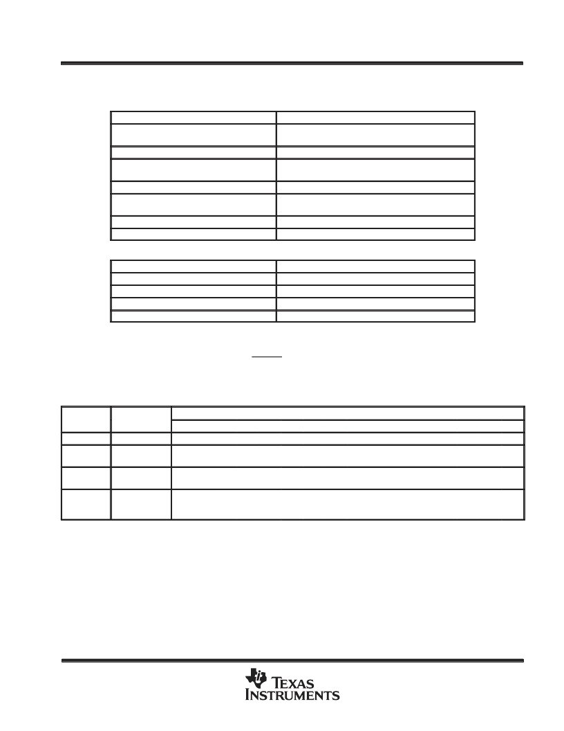
identification of the TVP3703
One of the two following sequences of micro port accesses identifies the existence of the TVP3703 in a graphics
system:
OPERATION
RESULT
Read any valid register other than pixel mask
(e.g., read I/O location 03C7h)
Resets the indirect access sequence
Read pixel mask (I/O location 03C6h) four times
Provides indirect access procedure
Write pixel mask with 10h
Provides indirect access to pixel command register, enabling
indexed registers. This also resets the indirect procedure.
Read pixel mask five times
Provides indirect access procedure
Write pixel mask twice with 00h
Provides indirect access procedure setting the index
registers to 0
Read pixel mask
Returns company ID (97h)
Read pixel mask
Returns device ID (03h)
or:
OPERATION
RESULT
Write zero to RS(2–0) = 4h
Sets the index low byte to zero
Write zero to RS(2–0) = 7h
Sets the index high byte to zero
Read RS(2–0) = 5h
Returns company ID (97h)
Read RS(2–0) = 5h
Returns device ID (03h)
pixel port
The rising edge of PCLK latches all of the pixels. Modes requiring more than one word per pixel accumulate
the least significant bytes of the pixel first. BLANK going high always identifies the first word within a pixel. The
VGA, SVGA, and extended pixel modes are listed in Tables 5 and 6.
Table 5. VGA and SVGA Modes
SVGA
MODE
PIXEL WORD
LATCHED
USE OF PIXEL INPUT TERMINALS
P15
X
P14
X
P13
X
P12
X
P11
X
P10
X
P9
X
P8
X
P7
P7
P6
P6
P5
P5
P4
P4
P3
P3
P2
P2
P1
P1
P0
P0
8-bit indexed
single P(7–0)
15-bit direct
(5–5–5)
first P(7–0)
second P(7–0)
X
X
X
X
X
X
X
X
X
X
X
X
X
X
X
X
G5
X
G4
R7
G3
R6
B7
R5
B6
R4
B5
R3
B4
G7
B3
G6
16-bit direct
(5–6–5)
first P(7–0)
second P(7–0)
X
X
X
X
X
X
X
X
X
X
X
X
X
X
X
X
G4
R7
G3
R6
G2
R5
B7
R4
B6
R3
B5
G7
B4
G6
B3
G5
24-bit direct
(8–8–8)
first P(7–0)
second P(7–0)
third P(7–0)
X
X
X
X
X
X
X
X
X
X
X
X
X
X
X
X
X
X
X
X
X
X
X
X
B7
G7
R7
B6
G6
R6
B5
G5
R5
B4
G4
R4
B3
G3
R3
B2
G2
R2
B1
G1
R1
B0
G0
R0
Pipe delay for all modes = 3 PCLK + 7 dot clocks
Unspecified bits = 0
相關(guān)PDF資料 |
PDF描述 |
|---|---|
| TVP5020TQFP | NTSC/PAL VIDEO DECODER |
| TVP5031 | NTSC/PAL VIDEO DECODER |
| TVP5031TQFP | NTSC/PAL VIDEO DECODER |
| TVP5031CPFP | Color Decoder Circuit |
| TVR4J | TOSHIBA Fast Recovery Diode Silicon Diffused Type High Speed Rectifier Applications (fast recovery) |
相關(guān)代理商/技術(shù)參數(shù) |
參數(shù)描述 |
|---|---|
| TVP4020AGFN | 制造商:Rochester Electronics LLC 功能描述:- Bulk 制造商:Texas Instruments 功能描述: |
| TVP4020AGFN-8 | 制造商:Rochester Electronics LLC 功能描述:- Bulk 制造商:Texas Instruments 功能描述: |
| TVP5010 | 制造商:TI 制造商全稱:Texas Instruments 功能描述:NTSC/PAL Video Decoder |
| TVP5010CPFP | 制造商:Rochester Electronics LLC 功能描述:- Bulk |
| TVP5020 | 制造商:TI 制造商全稱:Texas Instruments 功能描述:NTSC/PAL VIDEO DECODER |
發(fā)布緊急采購,3分鐘左右您將得到回復(fù)。