- 您現(xiàn)在的位置:買(mǎi)賣(mài)IC網(wǎng) > PDF目錄373749 > TWL2214CA High voltage fast-switching NPN power transistor PDF資料下載
參數(shù)資料
| 型號(hào): | TWL2214CA |
| 英文描述: | High voltage fast-switching NPN power transistor |
| 中文描述: | 電源管理IC和鋰離子電池充電控制 |
| 文件頁(yè)數(shù): | 9/36頁(yè) |
| 文件大小: | 511K |
| 代理商: | TWL2214CA |
第1頁(yè)第2頁(yè)第3頁(yè)第4頁(yè)第5頁(yè)第6頁(yè)第7頁(yè)第8頁(yè)當(dāng)前第9頁(yè)第10頁(yè)第11頁(yè)第12頁(yè)第13頁(yè)第14頁(yè)第15頁(yè)第16頁(yè)第17頁(yè)第18頁(yè)第19頁(yè)第20頁(yè)第21頁(yè)第22頁(yè)第23頁(yè)第24頁(yè)第25頁(yè)第26頁(yè)第27頁(yè)第28頁(yè)第29頁(yè)第30頁(yè)第31頁(yè)第32頁(yè)第33頁(yè)第34頁(yè)第35頁(yè)第36頁(yè)
SLVS321A
–
OCTOBER 2001
–
REVISED JANUARY 2002
9
POST OFFICE BOX 655303
DALLAS, TEXAS 75265
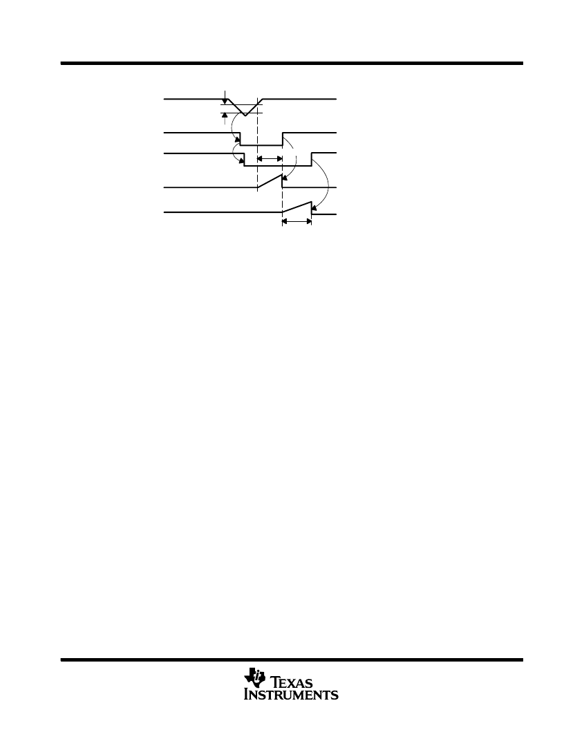
detailed description (continued)
VREG1
XRST
PSH
CD1
CD2
To keep power-on condition PSH must be
high within maximum CD2 delay.
CD1 delay
0.9 VOUT
Hysteresis
Figure 4. V
REG1
Monitoring of Reset Control
regulator 1
This regulator is automatically enabled after the power-on process is complete. It stays enabled until the
power-off condition occurs. Regulator 1 supplies power to the microprocessor. The nominal output voltage is
2.8 V and the maximum output current is 150 mA. Regulator 1 requires an output capacitor in the range of 4.7
μ
F
to10
μ
F with an ESR less than 6
.
regulator 6
This regulator output voltage can be enabled by I
2
C by attaching CONT (terminal 21 or H6) to V
DD
. Attaching
CONT to GND makes this regulator automatically enabled with power on. The output voltage is programmed
by I
2
C. The maximum output current of 100 mA requires an output capacitor in range of 4.7
μ
F to 10
μ
F, with
ESR in the range of 1
to
6
.
The output voltage ranges from 2.5 V to 3 V.
regulators 2, 3, 4, and 5
Regulators 2, 3, 4, and 5 are output voltages programmed and enabled by I
2
C. The output voltage ranges from
2.3 V to 3 V in 100-mV steps. The maximum output current for regulators 2 and 3 is 80 mA, for regulator 4 it
is 120 mA, and for regulator 5 it is 150 mA. The default output voltage for all regulators is 3 V. These regulators
have very low output noise (maximum 30
μ
V
RMS
); they are suitable for powering up the RF block, which requires
an output capacitor in the range of 4.7
μ
F to 10
μ
F with an ESR less than 6
.
vibrator driver
The TWL2214CA device has incorporated a vibrator driver with selectable output voltage and current. This
integrated vibrator driver has the same features as the other LDO regulators. The vibrator is enabled by I
2
C.
The output voltage can be selected by tying SEL (terminal 4 or D2) to V
DD
or GND. If SEL is tied to V
, the
output voltage is set to 3 V. If SEL is tied to GND, the output voltage is set to 1.3 V.
LED driver
The TWL2214CA device provides the capability of driving three LEDs. These drivers, enabled by I
2
C, can drive
currents of 160 mA, 20 mA, and 10 mA individually with a maximum voltage drop of 0.8 V.
ringer driver
The TWL2214CA device provides the capability of driving a ringer. It is enabled by I
2
C and uses an N-channel
FET with a maximum resistance of 3
.
相關(guān)PDF資料 |
PDF描述 |
|---|---|
| TX-1033S | TX-1033S |
| TX-S | SMALL POLARIZED RELAY WITH HIGH SENSITIVITY 50mW |
| TXC-20049-DCMM | N-channel 25V - 0.0068O - 60A - DPAK - IPAK STripFET™ III Power MOSFET |
| TXC-20153-DCMM | N-channel 30V - 0.0059 Ohm - 70A - DPAK / IPAK STripFET III Power MOSFET |
| TXC06303AIBG | N-CHANNEL 24V - 0.010 Ohm - 40A DPAK/IPAK ULTRA LOW GATE CHARGE STRIPFET POWER MOSFET |
相關(guān)代理商/技術(shù)參數(shù) |
參數(shù)描述 |
|---|---|
| TWL2214CAPFB | 制造商:Rochester Electronics LLC 功能描述:POWER SUPPLY MANAGEMENT IC:LION - Bulk 制造商:Texas Instruments 功能描述:CHGR LI-ION/LI-POL 150MA 2.8V 48TQFP - Tape and Reel |
| TWL2214CAPFBR | 制造商:Rochester Electronics LLC 功能描述:POWER SUPPLY MANAGEMENT IC:LION - Bulk 制造商:Texas Instruments 功能描述:CHGR LI-ION/LI-POL 150MA 2.8V 48TQFP - Tape and Reel |
| TWL2217CGGMR | 制造商:Texas Instruments 功能描述: |
| TWL2217CZQER | 制造商:Texas Instruments 功能描述: |
| TWL3014CGGMR | 制造商:Fairchild Semiconductor Corporation 功能描述: |
發(fā)布緊急采購(gòu),3分鐘左右您將得到回復(fù)。