- 您現(xiàn)在的位置:買賣IC網 > PDF目錄379479 > UCC28510-17 (Texas Instruments, Inc.) ADVANCED PFC/PWW COMBINATION CONTROLLER WITH TRAILING-EDGE/TRAILING-EDGE MODULATION PDF資料下載
參數資料
| 型號: | UCC28510-17 |
| 廠商: | Texas Instruments, Inc. |
| 元件分類: | 基準電壓源/電流源 |
| 英文描述: | ADVANCED PFC/PWW COMBINATION CONTROLLER WITH TRAILING-EDGE/TRAILING-EDGE MODULATION |
| 中文描述: | 高級式PFC / PWW組合控制器,TRAILING-EDGE/TRAILING-EDGE調制 |
| 文件頁數: | 20/39頁 |
| 文件大小: | 725K |
| 代理商: | UCC28510-17 |
第1頁第2頁第3頁第4頁第5頁第6頁第7頁第8頁第9頁第10頁第11頁第12頁第13頁第14頁第15頁第16頁第17頁第18頁第19頁當前第20頁第21頁第22頁第23頁第24頁第25頁第26頁第27頁第28頁第29頁第30頁第31頁第32頁第33頁第34頁第35頁第36頁第37頁第38頁第39頁
SLUS517B DECEMBER 2002 REVISED AUGUST 2004
20
www.ti.com
APPLICATION INFORMATION
The selection process begins with the selection of R1 so that the peak I
AC
current at high ac line is about 500
μ
A,
see Table 2. Second, select R15 for the minimum VFF voltage, also shown in Table 2. Third, select C8, in Table
2, to average the VFF voltage with sufficiently low ripple to meet a third harmonic distortion budget. For a system
with a 3% THD target, it is typical to allow the feedforward circuit to contribute 1.5% third harmonic distortion
to the input waveform [4]. An attenuation factor of 0.022 will meet the criteria. Finally, select the MOUT resistor
in Table 2, R12, so that the voltage across R12 equals the voltage across sense resistor R2 under the condition
of maximum power, minimum ac line voltage (V
VFF, MIN
), and VAOUT at its maximum level of 5 V. Experimentally,
the multiplier output resistor, R12, may need to be increased slightly if the energy storage capacitor voltage sags
under maximum load. This would be due to tolerances in the components and the multiplier. In order to minimize
current amplifier offsets, set the value of the resistor on the ISENSE1 pin, R8, equal to the value of R12 as shown
in in Table 2.
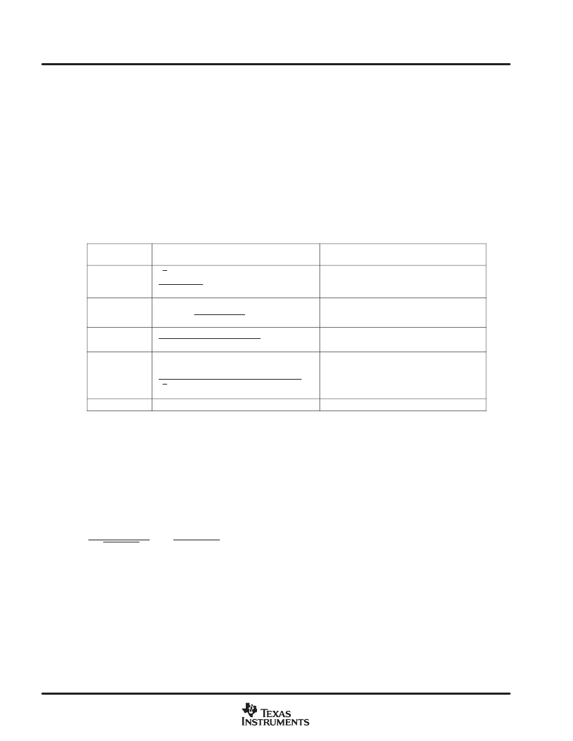
Table 2.
REFERENCE
DESIGNATOR
EQUATION
NOTES
R1
2VAC(max)
IIAC(peak)
set iIAC(peak)
500 A
R15
2
R1
VVFF(avgmin)
VAC(min)
1
fAC
0.9
set V
VFF(avgmin)
1.4 V
C8
2
AFF(2)
R15
AFF(2)
0.022 for 3% THD
R12
Ipk
R1
R2
k
VFF(min)
2
2
VAC(min)
VVAOUT(max)
1 V
k = 1/V
VAC(min) = minimum RMS input voltage
VVFF(min) = 1.4V
VVAOUT(max) = 5.0V
R8
R12
Always change R8 if R12 is changed
PFC current loop control
This controller uses average current loop control for the PFC stage. The current control loop must typically be
fast enough to track the rectified sinusoidal ac line voltage. There are many ways to design a controller that will
stabilize the PFC current loop. The method that is described here achieves good results for most applications.
[5]
This method assumes that both the natural frequency of the system and the zero of the linearized boost PFC
are much lower than both the switching frequency and the desired crossover frequency, f
CO(pfc)
, as described
in equation 12. The left side of the inequality in equation 12 will usually be true since the capacitance of C1 is
quite large.
1
D
PWM(min)
L1
C1
and
2P
IN
C1
V
C1
2
2
f
CO(pfc)
2
f
S(pfc)
(12)
相關PDF資料 |
PDF描述 |
|---|---|
| UCC38517 | ADVANCED PFC/PWM COMBINA CONTROLLERS |
| UCC28517N | ADVANCED PFC/PWM COMBINATION CONTROLLERS |
| UCC2882-1 | Average Current Mode Synchronous Controller With 5-Bit DAC |
| UCC2882 | Average Current Mode Synchronous Controller With 5-Bit DAC |
| UCC2882- | Average Current Mode Synchronous Controller With 5-Bit DAC |
相關代理商/技術參數 |
參數描述 |
|---|---|
| UCC28510DW | 功能描述:功率因數校正 IC Advanced PFC/PWM Comb Controller RoHS:否 制造商:Fairchild Semiconductor 開關頻率:300 KHz 最大功率耗散: 最大工作溫度:+ 125 C 安裝風格:SMD/SMT 封裝 / 箱體:SOIC-8 封裝:Reel |
| UCC28510DWG4 | 功能描述:功率因數校正 IC Advanced PFC/PWM Comb Controller RoHS:否 制造商:Fairchild Semiconductor 開關頻率:300 KHz 最大功率耗散: 最大工作溫度:+ 125 C 安裝風格:SMD/SMT 封裝 / 箱體:SOIC-8 封裝:Reel |
| UCC28510DWR | 功能描述:功率因數校正 IC Advanced PFC/PWM Comb Controller RoHS:否 制造商:Fairchild Semiconductor 開關頻率:300 KHz 最大功率耗散: 最大工作溫度:+ 125 C 安裝風格:SMD/SMT 封裝 / 箱體:SOIC-8 封裝:Reel |
| UCC28510DWRG4 | 功能描述:功率因數校正 IC Advanced PFC/PWM Comb Controller RoHS:否 制造商:Fairchild Semiconductor 開關頻率:300 KHz 最大功率耗散: 最大工作溫度:+ 125 C 安裝風格:SMD/SMT 封裝 / 箱體:SOIC-8 封裝:Reel |
| UCC28510N | 功能描述:功率因數校正 IC Advanced PFC/PWM Comb Controller RoHS:否 制造商:Fairchild Semiconductor 開關頻率:300 KHz 最大功率耗散: 最大工作溫度:+ 125 C 安裝風格:SMD/SMT 封裝 / 箱體:SOIC-8 封裝:Reel |
發(fā)布緊急采購,3分鐘左右您將得到回復。