- 您現(xiàn)在的位置:買賣IC網(wǎng) > PDF目錄384045 > UPD72873 (NEC Corp.) MOS INTEGRATED CIRCUIT PDF資料下載
參數(shù)資料
| 型號: | UPD72873 |
| 廠商: | NEC Corp. |
| 英文描述: | MOS INTEGRATED CIRCUIT |
| 中文描述: | 馬鞍山集成電路 |
| 文件頁數(shù): | 23/40頁 |
| 文件大?。?/td> | 269K |
| 代理商: | UPD72873 |
第1頁第2頁第3頁第4頁第5頁第6頁第7頁第8頁第9頁第10頁第11頁第12頁第13頁第14頁第15頁第16頁第17頁第18頁第19頁第20頁第21頁第22頁當(dāng)前第23頁第24頁第25頁第26頁第27頁第28頁第29頁第30頁第31頁第32頁第33頁第34頁第35頁第36頁第37頁第38頁第39頁第40頁
Preliminary Data Sheet S15305EJ2V0DS
23
μ
PD72873
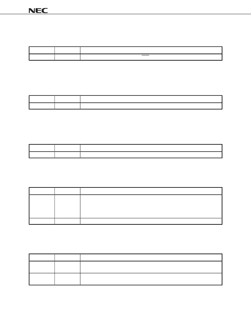
3.1.16 Offset_3D Interrupt Pin Register
This register provides the interrupt line routing information specific to the
μ
PD72873, the NEC’s implementation of
the 1394 OHCI specification.
Bits
R/W
Description
7-0
R
Constant value of 01H. It specifies PCI INTA is used for interrupting the host system.
3.1.17 Offset_3E Min_Gnt Register
This register specifies how long of a burst period the
μ
PD72873 needs, assuming a clock rate of 33 MHz.
Resolution is in units of
μ
s. The value should be loaded into the register from the external serial EEPROM upon
power-up reset, and access to this register through PCI-bus is prohibited.
Bits
R/W
Description
7-0
R
Default value of 00H. Its value contributes to the desired setting for Latency Timer value.
3.1.18 Offset_3F Max_Lat Register
This register specifies how often the
μ
PD72873 needs to gain access to the PCI-bus, assuming a clock rate of 33
MHz. Resolution is in units of
μ
s. The value should be loaded into the register from the external serial EEPROM
after hardware reset, and access to this register through PCI-bus is prohibited.
Bits
R/W
Description
7-0
R
Default value of 00H. Its value contributes to the desired setting for Latency Timer value.
3.1.19 Offset_40 PCI_OHCI_Control Register
This register specifies the control bits that are IEEE1394 OHCI specific. Vendor options are not allowed in this
register. It is reserved for OHCI use only.
Bits
R/W
Description
0
R/W
PCI global SWAP
Default value of 0. When this bit is 1, all quadrates read from and written to
the PCI Interface are byte swapped, thus a “PCI Global Swap”. PCI addresses for expansion
ROM and PCI Configuration registers, are, however, unaffected by this bit. This bit is not
required for motherboard implementations.
31-1
R
Reserved
Constant value of all 0.
3.1.20 Offset_60 Cap_ID & Next_Item_Ptr Register
The Cap_ID signals that this item in the Linked List is the registers defined for PCI Power Management, while the
Next_Item_Ptr describes the location of the next item in the
μ
PD72873’s Capability List.
Bits
R/W
Description
7-0
R
Cap_ID
Constant value of 01H. The default value identified the Link List item as being the PCI
Power Management registers, while the ID value is assigned by the PCI SIG.
15-8
R
Next_Item_Ptr
Constant value of 00H. It indicated that there are no more items in the Link
List.
相關(guān)PDF資料 |
PDF描述 |
|---|---|
| UPD72873GC-YEB | MOS INTEGRATED CIRCUIT |
| UPD72874 | IEEE1394 OHCI 1.1 COMPLIANT 3PORT PHY-LINK 1-CHIP HOST CONTROLLER |
| UPD72874GC-YEB | IEEE1394 OHCI 1.1 COMPLIANT 3PORT PHY-LINK 1-CHIP HOST CONTROLLER |
| UPD7281 | IEEE1394 OHCI 1.1 COMPLIANT 3PORT PHY-LINK 1-CHIP HOST CONTROLLER |
| UPD753036 | 4-BIT SINGLE-CHIP MICROCONTROLLER FOR SMALL GENERAL-PURPOSE INFRARED REMOTE CONTROL TRANSMITTER |
相關(guān)代理商/技術(shù)參數(shù) |
參數(shù)描述 |
|---|---|
| UPD74HC04C | 制造商:Panasonic Industrial Company 功能描述:IC |
| UPD750068GT-396 | 制造商:Renesas Electronics Corporation 功能描述: |
| UPD7507C189 | 制造商:Panasonic Industrial Company 功能描述:IC |
| UPD7508CU265 | 制造商:Panasonic Industrial Company 功能描述:IC |
| UPD75208 | 制造商:Panasonic Industrial Company 功能描述:IC |
發(fā)布緊急采購,3分鐘左右您將得到回復(fù)。