- 您現(xiàn)在的位置:買賣IC網(wǎng) > PDF目錄361790 > W741E200 4-Bit Microcontroller PDF資料下載
參數(shù)資料
| 型號(hào): | W741E200 |
| 英文描述: | 4-Bit Microcontroller |
| 中文描述: | 4位微控制器 |
| 文件頁(yè)數(shù): | 9/84頁(yè) |
| 文件大?。?/td> | 344K |
| 代理商: | W741E200 |
第1頁(yè)第2頁(yè)第3頁(yè)第4頁(yè)第5頁(yè)第6頁(yè)第7頁(yè)第8頁(yè)當(dāng)前第9頁(yè)第10頁(yè)第11頁(yè)第12頁(yè)第13頁(yè)第14頁(yè)第15頁(yè)第16頁(yè)第17頁(yè)第18頁(yè)第19頁(yè)第20頁(yè)第21頁(yè)第22頁(yè)第23頁(yè)第24頁(yè)第25頁(yè)第26頁(yè)第27頁(yè)第28頁(yè)第29頁(yè)第30頁(yè)第31頁(yè)第32頁(yè)第33頁(yè)第34頁(yè)第35頁(yè)第36頁(yè)第37頁(yè)第38頁(yè)第39頁(yè)第40頁(yè)第41頁(yè)第42頁(yè)第43頁(yè)第44頁(yè)第45頁(yè)第46頁(yè)第47頁(yè)第48頁(yè)第49頁(yè)第50頁(yè)第51頁(yè)第52頁(yè)第53頁(yè)第54頁(yè)第55頁(yè)第56頁(yè)第57頁(yè)第58頁(yè)第59頁(yè)第60頁(yè)第61頁(yè)第62頁(yè)第63頁(yè)第64頁(yè)第65頁(yè)第66頁(yè)第67頁(yè)第68頁(yè)第69頁(yè)第70頁(yè)第71頁(yè)第72頁(yè)第73頁(yè)第74頁(yè)第75頁(yè)第76頁(yè)第77頁(yè)第78頁(yè)第79頁(yè)第80頁(yè)第81頁(yè)第82頁(yè)第83頁(yè)第84頁(yè)
Preliminary W741E20X
Publication Release Date: March 1998
- 9 -
Revision A1
Clock Generator
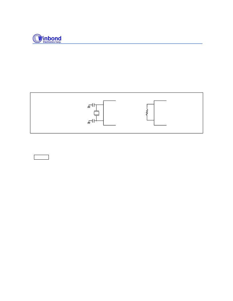
The W741E20X provides a crystal or RC oscillation circuit selected by option codes to generate the
system clock through external connections. If a crystal oscillator is used, a crystal or a ceramic
resonator must be connected to XIN and XOUT, and the capacitor must be connected if an accurate
frequency is needed. When a crystal oscillator is used, a high-frequency clock (400 KHz to 4 MHz) or
low-frequency clock (32 KHz) can be selected for the system clock by means of option codes. If the
RC oscillator is used, a resistor in the range of 20 K
to 1.6 M
must be connected to XIN and XOUT,
as shown in Figure 3. The system clock frequency range is from 32 KHz to 4 MHz. One machine cycle
consists of a four-phase system clock sequence and can run up to 1
μ
S with a 4 MHz system clock.
XIN
XOUT
XIN
XOUT
or
Crystal
Resistor
32 KHz or
400K to 4MHz
Figure 3. Oscillator Configuration
Divider 0
Divider 0 is organized as a 14-bit binary up-counter designed to generate periodic interrupts, as shown
in Figure 4. When the system starts, the divider is incremented by each system clock (Fosc). When an
overflow occurs, the divider event flag is set to 1 (EVF.0 = 1). Then, if the divider interrupt enable flag
has been set (IEF.0 = 1), the interrupt is executed, while if the hold release enable flag has been set
(HEF.0 = 1), the hold state is terminated. The last 4-stage of the Divider 0 can be reset by executing
CLR DIVR0 instruction. If the oscillator is connected to the 32768 Hz crystal, the EVF.0 will be set to 1
periodically at each 500 mS interval.
Watchdog Timer (WDT)
The watchdog timer (WDT) is organized as a 4-bit up counter and is designed to protect the program
from unknown errors. The WDT is enable when the corresponding option code bit of the WDT is set to
1. If the WDT overflows, the chip will be reset. At initial reset, the input clock of the WDT is F
OSC
/1024.
The input clock of the WDT can be switched to F
OSC
/16384 (or F
OSC
/1024) by executing the SET
PMF, #08H (or CLR PMF, #08H) instruction. The contents of the WDT can be reset by the instruction
CLR WDT. In normal operation, the application program must reset WDT before it overflows. A WDT
overflow indicates that the operation is not under control and the chip will be reset. The WDT minimun
overflow period is 468.75 mS when the system clock (F
OSC
) is 32 KHz and WDT clock input is
F
OSC
/1024. When the corresponding option code bit of the WDT is set to 0, the WDT function is
disabled. The organization of the Divider0 and watchdog timer is shown in Figure 4.
相關(guān)PDF資料 |
PDF描述 |
|---|---|
| W742C(E)811 | 4-BIT MICROCONTROLLER |
| W742C816 | Microcontroller |
| W742C818 | Microcontroller |
| W742E816 | Microcontroller |
| W742C811 | 4-BIT MICROCONTROLLER |
相關(guān)代理商/技術(shù)參數(shù) |
參數(shù)描述 |
|---|---|
| W741E201 | 制造商:WINBOND 制造商全稱:Winbond 功能描述:4-BIT FLASH MICROCONTROLLER |
| W741E202 | 制造商:WINBOND 制造商全稱:Winbond 功能描述:4-BIT FLASH MICROCONTROLLER |
| W741E203 | 制造商:WINBOND 制造商全稱:Winbond 功能描述:4-BIT FLASH MICROCONTROLLER |
| W741E204 | 制造商:WINBOND 制造商全稱:Winbond 功能描述:4-BIT FLASH MICROCONTROLLER |
| W741E205 | 制造商:WINBOND 制造商全稱:Winbond 功能描述:4-BIT FLASH MICROCONTROLLER |
發(fā)布緊急采購(gòu),3分鐘左右您將得到回復(fù)。