- 您現(xiàn)在的位置:買賣IC網(wǎng) > PDF目錄372930 > XQR4013XL-3CB228M Field Programmable Gate Array (FPGA) PDF資料下載
參數(shù)資料
| 型號: | XQR4013XL-3CB228M |
| 英文描述: | Field Programmable Gate Array (FPGA) |
| 中文描述: | 現(xiàn)場可編程門陣列(FPGA) |
| 文件頁數(shù): | 3/20頁 |
| 文件大小: | 201K |
| 代理商: | XQR4013XL-3CB228M |
QPRO XQR4000XL Radiation Hardened FPGAs
DS071 (v1.1) June 25, 2000
Product Specification
This Material Copyrighted by Its Respective Manufacturer
www.xilinx.com
1-800-255-7778
3
R
XQR4000XL Switching Characteristics
Definition of Terms
In the following tables, some specifications may be designated as Advance or Preliminary. These terms are defined as
follows:
Advance:
Initial estimates based on simulation and/or extrapolation from other speed grades, devices, or
devicefamilies. Values are subject to change. Use as estimates, not for production.
Preliminary:
Based on preliminary characterization. Further changes are not expected.
Unmarked:
Specifications not identified as either Advance or Preliminary are to be considered Final.
Except for pin-to-pin input and output parameters, the AC parameter delay specifications included in this document are
derived from measuring internal test patterns. All specifications are representative of worst-case supply voltage and junction
temperature conditions.
All specifications subject to change without notice.
Additional Specifications
Except for pin-to-pin input and output parameters, the a.c.
parameter delay specifications included in this document
are derived from measuring internal test patterns. All speci-
fications are representative of worst-case supply voltage
and junction temperature conditions. The parameters
included are common to popular designs and typical appli-
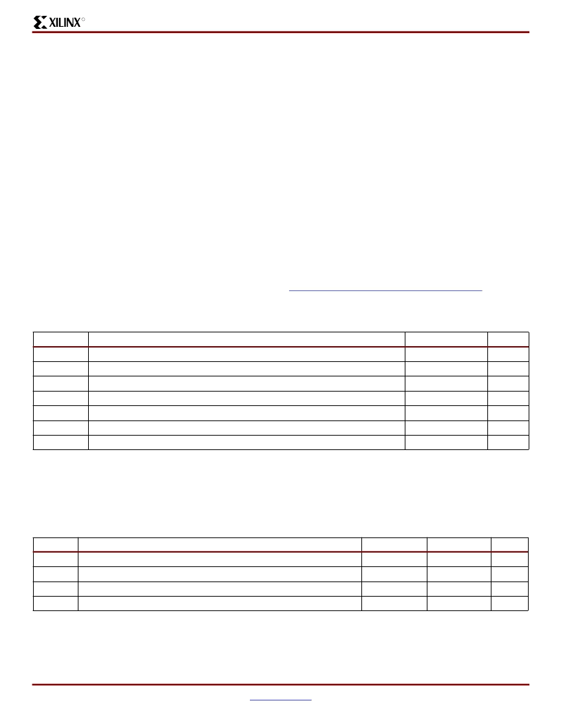
Absolute Maximum Ratings
(1)
cations. For design considerations requiring more detailed
timing information, see the appropriate family AC supple-
ments available on the Xilinx web site at:
.Recommended Operating Conditions
(1)
Symbol
V
CC
V
IN
V
TS
V
CCt
T
STG
T
SOL
T
J
Notes:
1.
Stresses beyond those listed under Absolute Maximum Ratings may cause permanent damage to the device. These are stress
ratings only, and functional operation of the device at these or any other conditions beyond those listed under Operating Conditions
is not implied. Exposure to Absolute Maximum Ratings conditions for extended periods of time may affect device reliability.
2.
Maximum DC overshoot or undershoot above V
or below GND must be limited to either 0.5V or 10 mA, whichever is easier to
achieve. During transitions, the device pins may undershoot to
–
2.0 V or overshoot to V
CC
+ 2.0V, provided this over- or undershoot
lasts less than 10 ns and with the forcing current being limited to 200 mA.
Description
Units
V
V
V
ms
°
C
°
C
°
C
Supply voltage relative to GND
Input voltage relative to GND
(2)
Voltage applied to High-Z output
(2)
Longest supply voltage rise time from 1V to 3V
Storage temperature (ambient)
Maximum soldering temperature (10s @ 1/16 in. = 1.5 mm)
Junction temperature
–
0.5 to 4.0
–
0.5 to 5.5
–
0.5 to 5.5
50
–
65 to +150
+260
+150
Symbol
V
CC
V
IH
V
IL
T
IN
Notes:
1.
At junction temperatures above those listed as Operating Conditions, all delay parameters increase by 0.35% per
°
C.
2.
Input and output measurement threshold is ~50% of V
CC
.
Description
Min
3.0
Max
3.6
5.5
Units
V
V
V
ns
Supply voltage relative to GND, T
C
=
–
55
°
C to +125
°
C
High-level input voltage
(2)
Low-level input voltage
Input signal transition time
50% of V
CC
0
-
30% of V
CC
250
相關(guān)PDF資料 |
PDF描述 |
|---|---|
| XQR4036XL-3CB228M | Field Programmable Gate Array (FPGA) |
| XQR4062XL-3CB228M | Field Programmable Gate Array (FPGA) |
| XR-082CP | Voltage-Feedback Operational Amplifier |
| XR-082M | Voltage-Feedback Operational Amplifier |
| XR-082N | Voltage-Feedback Operational Amplifier |
相關(guān)代理商/技術(shù)參數(shù) |
參數(shù)描述 |
|---|---|
| XQS14+A2FZ | 制造商:Panasonic Industrial Company 功能描述:SCREW (1/10) |
| XQS2+A5FZ | 制造商:Panasonic Industrial Company 功能描述:SCREW |
| XQS2+AJ8FZ | 制造商:Panasonic Industrial Company 功能描述:SCREW |
| XQT2LMR11D | 制造商:SunLED Group 功能描述: |
| XQT2LUG11D | 制造商:SunLED Group 功能描述: |
發(fā)布緊急采購,3分鐘左右您將得到回復(fù)。