- 您現(xiàn)在的位置:買賣IC網(wǎng) > PDF目錄16433 > XR16V698IQ-0B-EVB (Exar Corporation)EVAL BOARD FOR XR16V698-B 100QFP PDF資料下載
參數(shù)資料
| 型號(hào): | XR16V698IQ-0B-EVB |
| 廠商: | Exar Corporation |
| 文件頁(yè)數(shù): | 19/58頁(yè) |
| 文件大小: | 0K |
| 描述: | EVAL BOARD FOR XR16V698-B 100QFP |
| 標(biāo)準(zhǔn)包裝: | 1 |
| 系列: | * |
第1頁(yè)第2頁(yè)第3頁(yè)第4頁(yè)第5頁(yè)第6頁(yè)第7頁(yè)第8頁(yè)第9頁(yè)第10頁(yè)第11頁(yè)第12頁(yè)第13頁(yè)第14頁(yè)第15頁(yè)第16頁(yè)第17頁(yè)第18頁(yè)當(dāng)前第19頁(yè)第20頁(yè)第21頁(yè)第22頁(yè)第23頁(yè)第24頁(yè)第25頁(yè)第26頁(yè)第27頁(yè)第28頁(yè)第29頁(yè)第30頁(yè)第31頁(yè)第32頁(yè)第33頁(yè)第34頁(yè)第35頁(yè)第36頁(yè)第37頁(yè)第38頁(yè)第39頁(yè)第40頁(yè)第41頁(yè)第42頁(yè)第43頁(yè)第44頁(yè)第45頁(yè)第46頁(yè)第47頁(yè)第48頁(yè)第49頁(yè)第50頁(yè)第51頁(yè)第52頁(yè)第53頁(yè)第54頁(yè)第55頁(yè)第56頁(yè)第57頁(yè)第58頁(yè)

XR16V698
26
2.25V TO 3.6V HIGH PERFORMANCE OCTAL UART WITH 32-BYTE FIFO
REV. 1.0.3
3.1.2
General Purpose 16-bit Timer/Counter [TIMERMSB, TIMELSB, TIMER, TIMECNTL] (DEFAULT
0XXX-XX-00-00)
The 698 includes a 16-bit general purpose timer/counter. Its clock source may be selected from internal crystal
oscillator or externally on pin TMRCK. The timer can be set to be a single-shot for a one-time event or re-
triggerable for a periodic signal. An interrupt may be generated when the timer times out and will show up as a
Channel 0 interrupt (see Table 9). It is controlled through 4 configuration registers [TIMERCNTL, TIMER,
TIMELSB, TIMERMSB]. These registers provide start/stop and re-triggerable or one-shot operation (see
below). The time-out output of the Timer can be set to generate an interrupt for system or event
alarm.
3.1.2.1
TIMERMSB [7:0] and TIMERLSB [7:0]
TIMERMSB and TIMERLSB form a 16-bit value. The least-significant bit of the timer is being bit-0 of the
TIMERLSB with most-significant-bit being bit-7 in TIMERMSB. Notice that these registers do not hold the
current counter value when read. Default value is zero (timer disabled) upon powerup and reset.
3.1.2.2
TIMER [7:0] Reserved
3.1.2.3
TIMERCNTL [7:0] Register
The bits 3:0 of this register are used to issue commands. The commands are self-clearing, so reading this
register does not show the last written command. Reading this register returns a value of 0x01 when there is a
Timer interrupt pending and 0x00 at all other times.
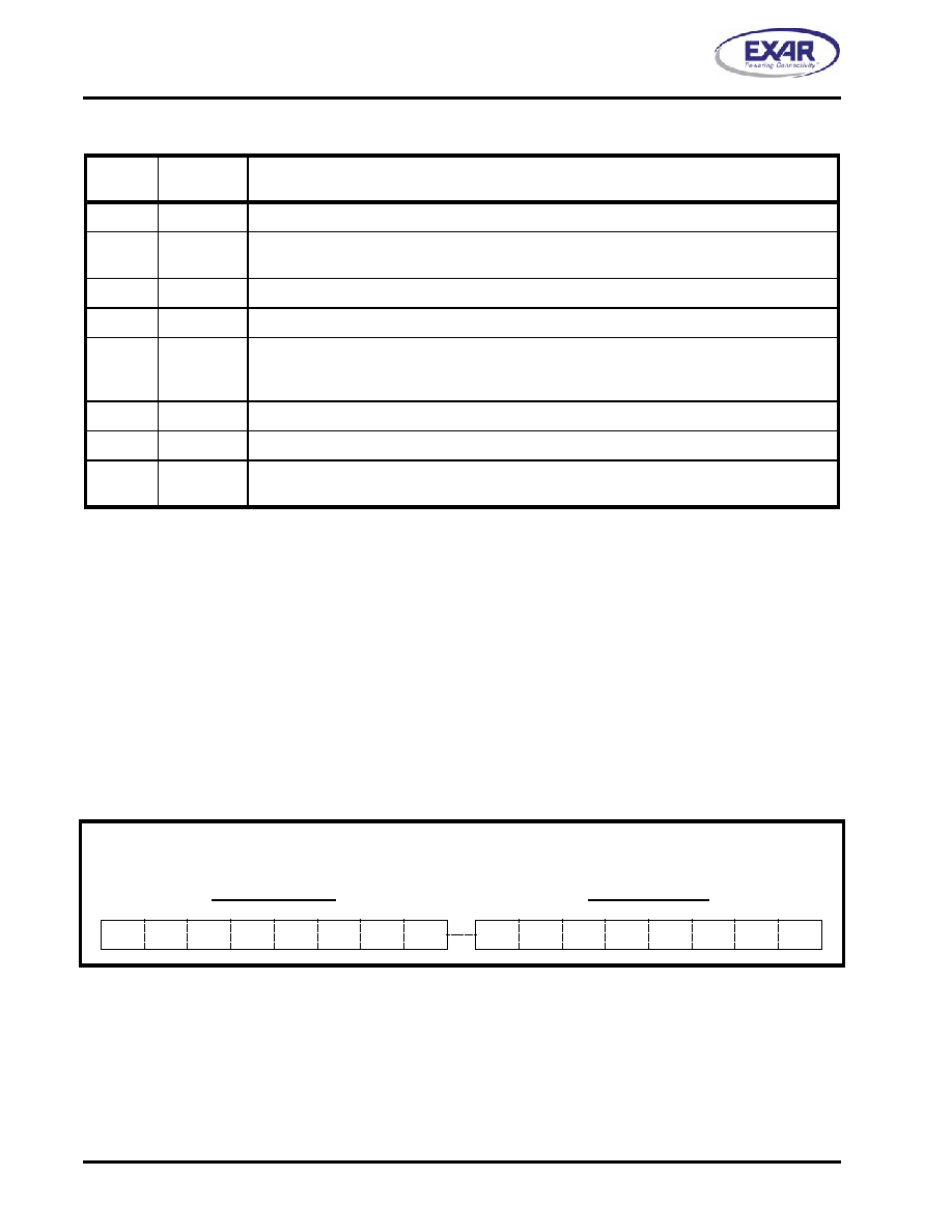
TABLE 9: UART CHANNEL [7:0] INTERRUPT SOURCE ENCODING AND CLEARING
PRIORITY
Bit
2
Bit
1
Bit
0
INTERRUPT SOURCE(S) AND CLEARING
x
0
None or wake-up indicator
1
0
1
RXRDY & RX Line Status (logic OR of LSR[4:1]). RXRDY INT clears by reading data in the RX
FIFO until it falls below the trigger level; RX Line Status INT cleared after reading LSR register.
2
0
1
0
RXRDY Time-out: Cleared same way as RXRDY INT.
3
0
1
TXRDY, THR or TSR (auto RS-485 mode) empty, clears after reading ISR register.
4
1
0
MSR, RTS/CTS or DTR/DSR delta or Xoff/Xon or special character detected. The first two
clears after reading MSR register; Xoff/Xon or special char. detect INT clears after reading ISR
register.
5
1
0
1
Reserved.
6
1
0
Reserved.
7
1
TIMER Time-out, shows up as a channel 0 INT. It clears after reading the TIMERCNTL register.
Reserved in other channels.
TIMERMSB Register
Bit-15 Bit-14 Bit-13 Bit-12 Bit-11 Bit-10
Bit-9 Bit-8
TIMERLSB Register
Bit-7
Bit-6
Bit-5
Bit-4
Bit-3
Bit-2
Bit-1 Bit-0
16-Bit Timer/Counter Programmable Registers
相關(guān)PDF資料 |
PDF描述 |
|---|---|
| XR16V698IQ-0A-EVB | EVAL BOARD FOR XR16V698-A 100QFP |
| KIT33972AEWEVBE | KIT EVALUATION FOR MC33972 |
| EBM31DCMS | CONN EDGECARD 62POS .156 WW |
| VI-J1L-EX | CONVERTER MOD DC/DC 28V 75W |
| XR16V598IQ-0B-EVB | EVAL BOARD FOR XR16V598-A 100QFP |
相關(guān)代理商/技術(shù)參數(shù) |
參數(shù)描述 |
|---|---|
| XR16V698IQ100 | 制造商:EXAR 制造商全稱:EXAR 功能描述:2.25V TO 3.6V HIGH PERFORMANCE OCTAL UART WITH 32-BYTE FIFO |
| XR16V698IQ100-F | 功能描述:UART 接口集成電路 UART RoHS:否 制造商:Texas Instruments 通道數(shù)量:2 數(shù)據(jù)速率:3 Mbps 電源電壓-最大:3.6 V 電源電壓-最小:2.7 V 電源電流:20 mA 最大工作溫度:+ 85 C 最小工作溫度:- 40 C 封裝 / 箱體:LQFP-48 封裝:Reel |
| XR16V698IQ100TR-F | 制造商:Exar Corporation 功能描述:UART 8-CH 32Byte FIFO 2.5V/3.3V 100-Pin PQFP T/R 制造商:Exar Corporation 功能描述:XR16V698IQ100TR-F |
| XR16V794 | 制造商:EXAR 制造商全稱:EXAR 功能描述:HIGH PERFORMANCE 2.25V TO 3.6V QUAD UART WITH FRACTIONAL |
| XR16V794_08 | 制造商:EXAR 制造商全稱:EXAR 功能描述:HIGH PERFORMANCE 2.25V TO 3.6V QUAD UART WITH FRACTIONAL |
發(fā)布緊急采購(gòu),3分鐘左右您將得到回復(fù)。