- 您現(xiàn)在的位置:買賣IC網(wǎng) > PDF目錄16428 > XR17V254IV-0A-EVB (Exar Corporation)EVAL BOARD FOR XR17V254 144LQFP PDF資料下載
參數(shù)資料
| 型號: | XR17V254IV-0A-EVB |
| 廠商: | Exar Corporation |
| 文件頁數(shù): | 4/70頁 |
| 文件大小: | 0K |
| 描述: | EVAL BOARD FOR XR17V254 144LQFP |
| 標準包裝: | 1 |
| 系列: | * |
第1頁第2頁第3頁當前第4頁第5頁第6頁第7頁第8頁第9頁第10頁第11頁第12頁第13頁第14頁第15頁第16頁第17頁第18頁第19頁第20頁第21頁第22頁第23頁第24頁第25頁第26頁第27頁第28頁第29頁第30頁第31頁第32頁第33頁第34頁第35頁第36頁第37頁第38頁第39頁第40頁第41頁第42頁第43頁第44頁第45頁第46頁第47頁第48頁第49頁第50頁第51頁第52頁第53頁第54頁第55頁第56頁第57頁第58頁第59頁第60頁第61頁第62頁第63頁第64頁第65頁第66頁第67頁第68頁第69頁第70頁

XR17V254
12
66MHZ PCI BUS QUAD UART WITH POWER MANAGEMENT SUPPORT
REV. 1.0.1
D3
COLD STATE
The V254 enters the state when power is removed from the device. All context is lost in this state and the V254
does not support PME# in this state. When power is restored, PCI RST# must be asserted and the V254 will
return to the D0 Uninitialized state with a full PCI 3.0 compliant power-on reset sequence. The V254 will set all
its registers and outputs to the power-on defaults just as at initial power up. The system software must then
fully initialize and re-configure the V254 to place it in the D0 Active state.
1.3
Special Read/Write Register to store User Information
This 32-bit register can be used to store user information and is writable only via the EEPROM. This is
implemented at an offset of 0x48 in the PCI Configuration Space immediately following the Power
Management Registers. This register can be used to store application-specific information which may be used
by the device driver to initialize the device appropriately.
NOTE: EWR=Read/Write from external EEPROM.
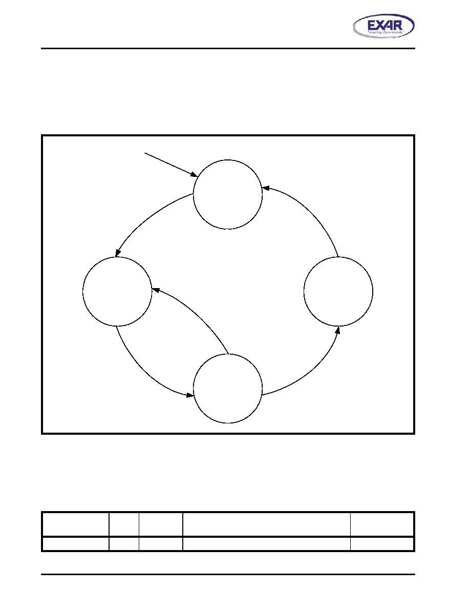
FIGURE 4. POWER STATE TRANSITIONS OF THE XR17V254
TABLE 3: SPECIAL READ/WRITE REGISTER
ADDRESS OFFSET
BITS
TYPE
DESCRIPTION
RESET VALUE
(HEX)
0x48
31:0
EWR
User Information Writable only through EEPROM
0x00000000
D0
Uninitialized
D3
hot
D3
cold
D0
Active
Power on +
PCI RST#
Power on +
PCI RST#
VCC Removed
相關(guān)PDF資料 |
PDF描述 |
|---|---|
| RPS0J102MCN1GS | CAP ALUM 1000UF 6.3V 20% SMD |
| EMM10DRMN | CONN EDGECARD 20POS .156 WW |
| GBA31DRMN-S288 | CONN EDGECARD 62POS .125 EXTEND |
| CM100505-18NGL | INDUCTOR CHIP 18NH 1005 SMD |
| 1-6828247-5 | CA,SM,MTRJ-SC |
相關(guān)代理商/技術(shù)參數(shù) |
參數(shù)描述 |
|---|---|
| XR17V254IV-F | 功能描述:UART 接口集成電路 66MHz Quad PCI UART RoHS:否 制造商:Texas Instruments 通道數(shù)量:2 數(shù)據(jù)速率:3 Mbps 電源電壓-最大:3.6 V 電源電壓-最小:2.7 V 電源電流:20 mA 最大工作溫度:+ 85 C 最小工作溫度:- 40 C 封裝 / 箱體:LQFP-48 封裝:Reel |
| XR17V258 | 制造商:EXAR 制造商全稱:EXAR 功能描述:66MHZ PCI BUS OCTAL UART WITH POWER MANAGEMENT SUPPORT |
| XR17V258_08 | 制造商:EXAR 制造商全稱:EXAR 功能描述:66MHZ PCI BUS OCTAL UART WITH POWER MANAGEMENT SUPPORT |
| XR17V258IV | 功能描述:UART 接口集成電路 66MHz Octal PCI UART RoHS:否 制造商:Texas Instruments 通道數(shù)量:2 數(shù)據(jù)速率:3 Mbps 電源電壓-最大:3.6 V 電源電壓-最小:2.7 V 電源電流:20 mA 最大工作溫度:+ 85 C 最小工作溫度:- 40 C 封裝 / 箱體:LQFP-48 封裝:Reel |
| XR17V258IV-0A-EVB | 功能描述:UART 接口集成電路 Supports V258 144 ld TQFP, PCI Interface RoHS:否 制造商:Texas Instruments 通道數(shù)量:2 數(shù)據(jù)速率:3 Mbps 電源電壓-最大:3.6 V 電源電壓-最小:2.7 V 電源電流:20 mA 最大工作溫度:+ 85 C 最小工作溫度:- 40 C 封裝 / 箱體:LQFP-48 封裝:Reel |
發(fā)布緊急采購,3分鐘左右您將得到回復。