- 您現(xiàn)在的位置:買賣IC網(wǎng) > PDF目錄16989 > XRD9825EVAL (Exar Corporation)EVAL BOARD FOR XRD9825 PDF資料下載
參數(shù)資料
| 型號(hào): | XRD9825EVAL |
| 廠商: | Exar Corporation |
| 文件頁(yè)數(shù): | 29/33頁(yè) |
| 文件大小: | 0K |
| 描述: | EVAL BOARD FOR XRD9825 |
| 標(biāo)準(zhǔn)包裝: | 1 |
| 系列: | * |
第1頁(yè)第2頁(yè)第3頁(yè)第4頁(yè)第5頁(yè)第6頁(yè)第7頁(yè)第8頁(yè)第9頁(yè)第10頁(yè)第11頁(yè)第12頁(yè)第13頁(yè)第14頁(yè)第15頁(yè)第16頁(yè)第17頁(yè)第18頁(yè)第19頁(yè)第20頁(yè)第21頁(yè)第22頁(yè)第23頁(yè)第24頁(yè)第25頁(yè)第26頁(yè)第27頁(yè)第28頁(yè)當(dāng)前第29頁(yè)第30頁(yè)第31頁(yè)第32頁(yè)第33頁(yè)

XRD9825
5
Rev. 1.00
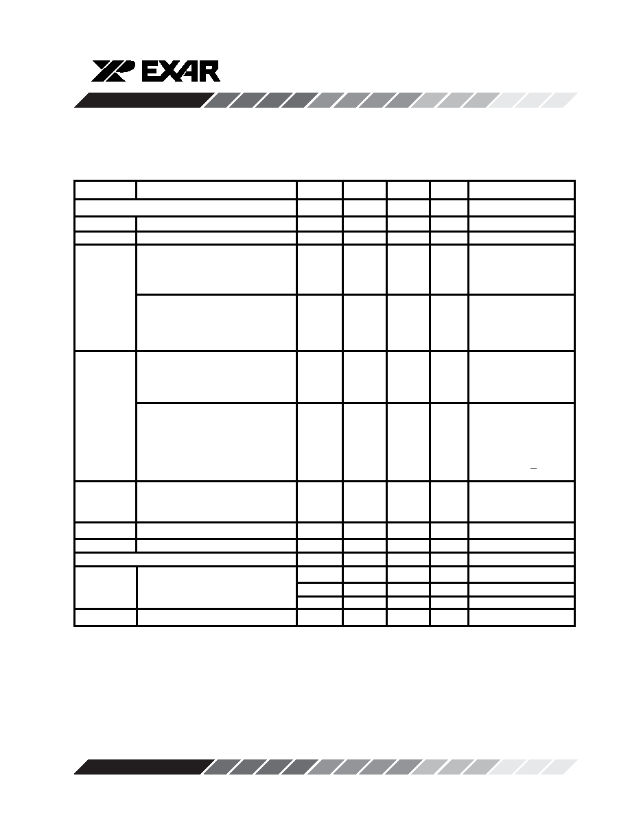
ELECTRICAL CHARACTERISTICS (CONT'D)
Test Conditions: AV
DD=DVDD=5V, ADCCLK=12MHz, 50% Duty Cycle, TA=25°C unless otherwise specified.
Symbol
Parameter
Min.
Typ.
Max.
Unit
Conditions
Buffer Specifications
I
IL
Input Leakage Current
100
nA
CIN
Input Capacitance
10
pF
VIN
PP
AC Input Voltage Range
0
AV
DD-1.4
V
CIS AC; INT V
DCREF
Config Reg
=> XXX010XX
Gain=1 (Note 1)
AC Input Voltage Range
0
V
REF
V
CCD AC; INT V
DCREF
Config Reg
=> XXX011XX
Gain=1 (Note 1)
VIN
DC Input Voltage Range
-0.1
AV
DD-1.4
V
CIS DC; INT V
DCREF
Config Reg
=> XXX000XX
Gain=1 (Note 2)
DC Input Voltage Range
V
DCEXT-0.1
V
DCEXT+
V
CIS DC; EXT V
DCREF
V
REF
Config Reg
=> XXX100XX
Gain=1 (Note 3)
V
DCEXT+DVREF < AVDD
V
DCEXT
External DC Reference
0.3
AV
DD/2
V
CIS DC; EXT V
DCREF
Config Reg
=> XXX100XX
VIN
BW
Input Bandwidth (small signal)
10
MHz
VIN
CT
Channel to Channel Crosstalk
-60
-50
dB
f
in=3MHz
Internal Clamp Specifications
V
CLAMP
Clamp Voltage
AGND
50
mV
CIS (AC) Config
3.5
V
RT
V
CCD (AC) Config
R
INT
Clamp Switch On Resistance
100
150
R
OFF
Clamp Switch Off Resistance
10
M
Note 1: VIN
PP is the signal swing before the external capacitor tied to the MUX inputs.
Note 2: The -0.1V minimum is specified in order to accommodate black level signals lower than the external DC
reference (clamp) voltage.
Note 3: The V
DCEXT-0.1V minimum is specified in order to accommodate black level signals lower than the external DC
reference voltage.
相關(guān)PDF資料 |
PDF描述 |
|---|---|
| EBM25DREH | CONN EDGECARD 50POS .156 EYELET |
| HSC07DREI | CONN EDGECARD 14POS .100 EYELET |
| XRD98L61EVAL | EVAL BOARD FOR XRD98L61AIV |
| EBM18DREH | CONN EDGE DUAL .156 PCB 36POS |
| MAX34406EVKIT# | KIT EVAL FOR MAX34406 |
相關(guān)代理商/技術(shù)參數(shù) |
參數(shù)描述 |
|---|---|
| XRD9826 | 制造商:EXAR 制造商全稱:EXAR 功能描述:16-Bit Linear CIS/CCD Sensor Signal Processor with Serial Control |
| XRD9826ACD | 制造商:EXAR 制造商全稱:EXAR 功能描述:16-Bit Linear CIS/CCD Sensor Signal Processor with Serial Control |
| XRD9826ACD-F | 功能描述:模數(shù)轉(zhuǎn)換器 - ADC RoHS:否 制造商:Texas Instruments 通道數(shù)量:2 結(jié)構(gòu):Sigma-Delta 轉(zhuǎn)換速率:125 SPs to 8 KSPs 分辨率:24 bit 輸入類型:Differential 信噪比:107 dB 接口類型:SPI 工作電源電壓:1.7 V to 3.6 V, 2.7 V to 5.25 V 最大工作溫度:+ 85 C 安裝風(fēng)格:SMD/SMT 封裝 / 箱體:VQFN-32 |
| XRD9826ACU | 功能描述:模數(shù)轉(zhuǎn)換器 - ADC RoHS:否 制造商:Texas Instruments 通道數(shù)量:2 結(jié)構(gòu):Sigma-Delta 轉(zhuǎn)換速率:125 SPs to 8 KSPs 分辨率:24 bit 輸入類型:Differential 信噪比:107 dB 接口類型:SPI 工作電源電壓:1.7 V to 3.6 V, 2.7 V to 5.25 V 最大工作溫度:+ 85 C 安裝風(fēng)格:SMD/SMT 封裝 / 箱體:VQFN-32 |
| XRD9826ACU-F | 功能描述:模數(shù)轉(zhuǎn)換器 - ADC RoHS:否 制造商:Texas Instruments 通道數(shù)量:2 結(jié)構(gòu):Sigma-Delta 轉(zhuǎn)換速率:125 SPs to 8 KSPs 分辨率:24 bit 輸入類型:Differential 信噪比:107 dB 接口類型:SPI 工作電源電壓:1.7 V to 3.6 V, 2.7 V to 5.25 V 最大工作溫度:+ 85 C 安裝風(fēng)格:SMD/SMT 封裝 / 箱體:VQFN-32 |
發(fā)布緊急采購(gòu),3分鐘左右您將得到回復(fù)。