- 您現(xiàn)在的位置:買賣IC網(wǎng) > PDF目錄376462 > XRT73R06 (Exar Corporation) SIX CHANNEL E3/DS3/STS-1 LINE INTERFACE UNIT PDF資料下載
參數(shù)資料
| 型號(hào): | XRT73R06 |
| 廠商: | Exar Corporation |
| 英文描述: | SIX CHANNEL E3/DS3/STS-1 LINE INTERFACE UNIT |
| 中文描述: | 六通道線路接口單元E3/DS3/STS-1 |
| 文件頁數(shù): | 19/68頁 |
| 文件大小: | 347K |
| 代理商: | XRT73R06 |
第1頁第2頁第3頁第4頁第5頁第6頁第7頁第8頁第9頁第10頁第11頁第12頁第13頁第14頁第15頁第16頁第17頁第18頁當(dāng)前第19頁第20頁第21頁第22頁第23頁第24頁第25頁第26頁第27頁第28頁第29頁第30頁第31頁第32頁第33頁第34頁第35頁第36頁第37頁第38頁第39頁第40頁第41頁第42頁第43頁第44頁第45頁第46頁第47頁第48頁第49頁第50頁第51頁第52頁第53頁第54頁第55頁第56頁第57頁第58頁第59頁第60頁第61頁第62頁第63頁第64頁第65頁第66頁第67頁第68頁

á
SIX CHANNEL E3/DS3/STS-1 LINE INTERFACE UNIT
XRT73R06
REV. 1.0.0
16
FUNCTIONAL DESCRIPTION
The XRT73R06 is a six channel fully integrated Line Interface Unit featuring EXAR’s R
3
Technology
(Reconfigurable, Relayless Redundancy) for E3/DS3/STS-1 applications. The LIU incorporates 6 independent
Receivers, Transmitters and Jitter Attenuators in a single 217 Lead BGA package. Each channel can be
independently programmed to support E3, DS-3 or STS-1 line rates using one input clock reference of
12.288MHz in Single Frequency Mode (SFM). The LIU is responsible for providing the physical connection
between a line interface and an aggregate mapper or framing device. Along with the analog-to-digital
processing, the LIU offers monitoring and diagnostic features to help optimize network design implementation.
A key characteristic within the network topology is Automatic Protection Switching (APS).
EXAR’s proven expertise in providing redundany solutions has paved the way for R
3
Technology.
1.0
R
3
TECHNOLOGY (RECONFIGURABLE, RELAYLESS REDUNDANCY)
Redundancy is used to introduce reliability and protection into network card design. The redundant card in
many cases is an exact replicate of the primary card, such that when a failure occurs the network processor
can automatically switch to the backup card. EXAR’s R
3
technology has re-defined E3/DS-3/STS-1 LIU design
for 1:1 and 1+1 redundancy applications. Without relays and one Bill of Materials, EXAR offers multi-port,
integrated LIU solutions to assist high density aggregate applications and framing requirements with reliability.
The following section can be used as a reference for implementing R
3
Technology with EXAR’s world leading
line interface units.
1.1
Network Architecture
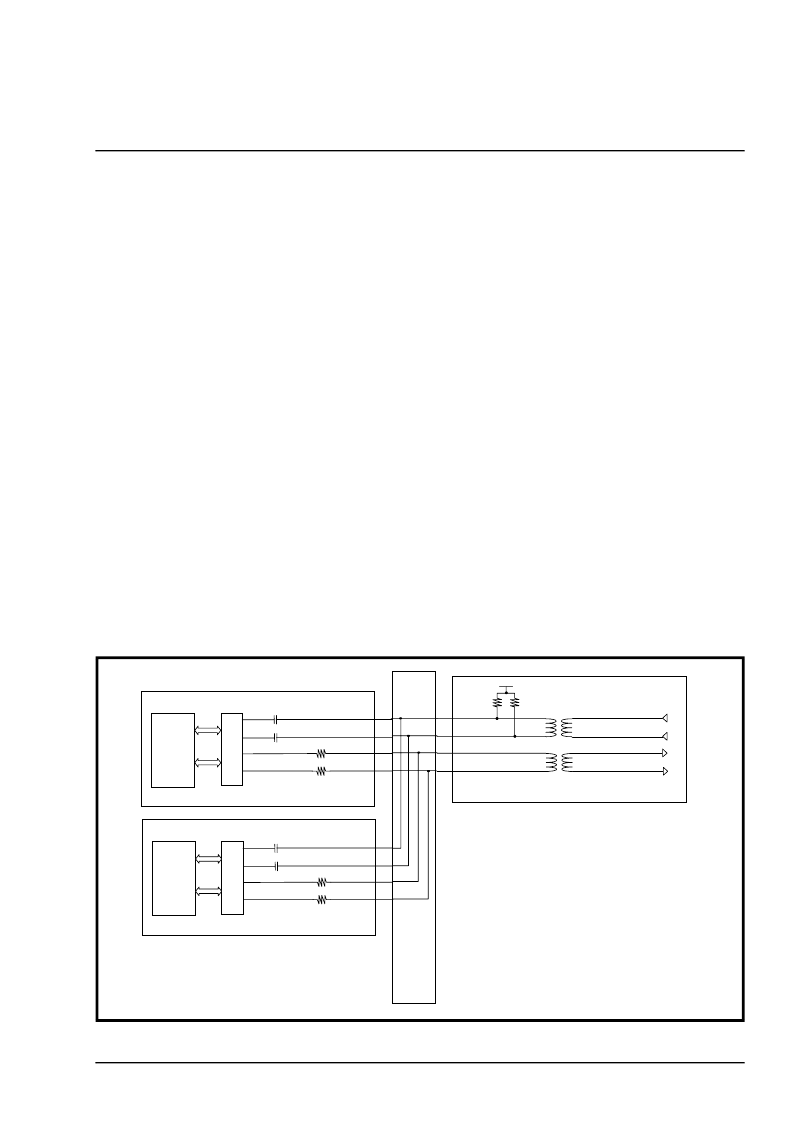
A common network design that supports 1:1 or 1+1 redundancy consists of N primary cards along with N
backup cards that connect into a mid-plane or back-plane architecture without transformers installed on the
network cards. In addition to the network cards, the design has a line interface card with one source of
transformers, connectors, and protection components that are common to both network cards. With this
design, the bill of materials is reduced to the fewest amount of components. See Figure 3. for a simplified
block diagram of a typical redundancy design.
F
IGURE
3. N
ETWORK
R
EDUNDANCY
A
RCHITECTURE
Line Interface Card
Primary Line Card
Framer/
Mapper
LIU
Back
Plane
or
Mid
Plane
Tx
Rx
31.6
31.6
0.01
μ
F
0.01
μ
F
1:1
1:1
Redundant Line Card
Framer/
Mapper
LIU
Tx
Rx
31.6
31.6
0.01
μ
F
0.01
μ
F
37.5
37.5
GND
相關(guān)PDF資料 |
PDF描述 |
|---|---|
| XRT73R06IB | SIX CHANNEL E3/DS3/STS-1 LINE INTERFACE UNIT |
| XRT73R12 | TWELVE CHANNEL E3/DS3/STS-1 LINE INTERFACE UNIT |
| XRT73R12IB | TWELVE CHANNEL E3/DS3/STS-1 LINE INTERFACE UNIT |
| XRT74L73 | 3 CHANNEL, ATM UNI/PPP DS3/E3 FRAMING CONTROLLER |
| XRT74L73IB | 3 CHANNEL, ATM UNI/PPP DS3/E3 FRAMING CONTROLLER |
相關(guān)代理商/技術(shù)參數(shù) |
參數(shù)描述 |
|---|---|
| XRT73R06ES | 功能描述:網(wǎng)絡(luò)控制器與處理器 IC RoHS:否 制造商:Micrel 產(chǎn)品:Controller Area Network (CAN) 收發(fā)器數(shù)量: 數(shù)據(jù)速率: 電源電流(最大值):595 mA 最大工作溫度:+ 85 C 安裝風(fēng)格:SMD/SMT 封裝 / 箱體:PBGA-400 封裝:Tray |
| XRT73R06IB | 功能描述:外圍驅(qū)動(dòng)器與原件 - PCI RoHS:否 制造商:PLX Technology 工作電源電壓: 最大工作溫度: 安裝風(fēng)格:SMD/SMT 封裝 / 箱體:FCBGA-1156 封裝:Tray |
| XRT73R06IB-F | 功能描述:外圍驅(qū)動(dòng)器與原件 - PCI RoHS:否 制造商:PLX Technology 工作電源電壓: 最大工作溫度: 安裝風(fēng)格:SMD/SMT 封裝 / 箱體:FCBGA-1156 封裝:Tray |
| XRT73R12 | 制造商:EXAR 制造商全稱:EXAR 功能描述:TWELVE CHANNEL E3/DS3/STS-1 LINE INTERFACE UNIT |
| XRT73R12_07 | 制造商:EXAR 制造商全稱:EXAR 功能描述:TWELVE CHANNEL E3/DS3/STS-1 LINE INTERFACE UNIT |
發(fā)布緊急采購,3分鐘左右您將得到回復(fù)。