- 您現(xiàn)在的位置:買賣IC網(wǎng) > PDF目錄373767 > Z86C6216PSC (ZILOG INC) CMOS Z8 MICROCONTROLLER PDF資料下載
參數(shù)資料
| 型號: | Z86C6216PSC |
| 廠商: | ZILOG INC |
| 元件分類: | 微控制器/微處理器 |
| 英文描述: | CMOS Z8 MICROCONTROLLER |
| 中文描述: | 8-BIT, MROM, 16 MHz, MICROCONTROLLER, PDIP64 |
| 封裝: | PLASTIC, DIP-64 |
| 文件頁數(shù): | 17/46頁 |
| 文件大小: | 388K |
| 代理商: | Z86C6216PSC |
第1頁第2頁第3頁第4頁第5頁第6頁第7頁第8頁第9頁第10頁第11頁第12頁第13頁第14頁第15頁第16頁當(dāng)前第17頁第18頁第19頁第20頁第21頁第22頁第23頁第24頁第25頁第26頁第27頁第28頁第29頁第30頁第31頁第32頁第33頁第34頁第35頁第36頁第37頁第38頁第39頁第40頁第41頁第42頁第43頁第44頁第45頁第46頁
17
Z86C61/62/96
Z8
M
ICROCONTROLLER
Port 3 can be configured under software control to provide
the following control functions: handshake for Ports 0 and
2 (/DAV and RDY); four external interrupt request signals
(IRQ3-IRQ0); timer input and output signals (T
IN
and T
OUT
),
and Data Memory Select (/DM).
D7
D6
D5
D4
D3
D2
D1
D0
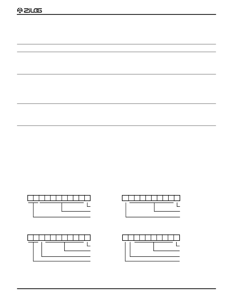
Start Bit
Eight Data Bits
Transmitted Data (No Parity)
Two Stop Bits
SP
SP
ST
D7
D6
D5
D4
D3
D2
D1
D0
Start Bit
Eight Data Bits
Received Data (No Parity)
One Stop Bit
SP
ST
P
D6
D5
D4
D3
D2
D1
D0
Start Bit
Seven Data Bits
Transmitted Data (With Parity)
Odd Parity
Two Stop Bits
SP
SP
ST
P
D6
D5
D4
D3
D2
D1
D0
Start Bit
Seven Data Bits
Received Data (With Parity)
Parity Error Flag
One Stop Bit
ST
SP
Figure 14. Serial Data Formats
Table 7. Port 3 Pin Assignments
Pin
I/O
CTC1
Int.
P0 HS
P1 HS
P2 HS
UART
Ext
P30
P31
P32
P33
IN
IN
IN
IN
IRQ3
IRQ2
IRQ0
IRQ1
Serial In
T
IN
D/R
D/R
D/R
P34
P35
P36
P37
T0
T1
OUT
OUT
OUT
OUT
R/D
DM
R/D
T
OUT
R/D
Serial Out
IRQ4
IRQ5
Notes:
HS = Handshake Signals
D = Data Available
R = Ready
UART OPERATION
Port 3 lines P30 and P37, can be programmed as serial
I/O lines for full-duplex serial asynchronous receiver/
transmitter operation. The bit rate is controlled by the
Counter/Timer0.
The Z86C61/62/96 automatically adds a start bit and two
stop bits to transmitted data (Figure 14). Odd parity is also
available as an option. Eight data bits are always transmit-
ted, regardless of parity selection. If parity is enabled, the
eighth bit is the odd parity bit. An interrupt request (IRQ4)
is generated on all transmitted characters.
Received data must have a start bit, eight data bits and at
least one stop bit. If parity is on, bit 7 of the received data
is replaced by a parity error flag. Received characters
generate the IRQ3 interrupt request.
Note:
UART function is only available in stardard timing
mode (i.e., P01M D5 = 0).
相關(guān)PDF資料 |
PDF描述 |
|---|---|
| Z86C96 | CMOS Z8 MICROCONTROLLER |
| Z86C6116PSC | TRANS NPN 400VCEO 7A TO-220F |
| Z86C9620VSC | CMOS Z8 MICROCONTROLLER |
| Z86D73 | 40/44 Pin Low Valtage Infrared OTP MCU(40/44 引腳低功耗紅外線一次可編程微控制器) |
| Z86D86 | 28 Pin Low Valtage Infrared MCU(28引腳低電壓一次可編程微控制器) |
相關(guān)代理商/技術(shù)參數(shù) |
參數(shù)描述 |
|---|---|
| Z86C6216VSC | 制造商:ZILOG 制造商全稱:ZILOG 功能描述:CMOS Z8 MICROCONTROLLER |
| Z86C63 | 制造商:ZILOG 制造商全稱:ZILOG 功能描述:CMOS Z8 32K ROM MICROCONTROLLER |
| Z86C64 | 制造商:ZILOG 制造商全稱:ZILOG 功能描述:CMOS Z8 32K ROM MICROCONTROLLER |
| Z86C65 | 制造商:ZILOG 制造商全稱:ZILOG 功能描述:CMOS Z8 32KROMMICROCONTROLLER |
| Z86C6516PSC | 制造商:未知廠家 制造商全稱:未知廠家 功能描述:8-Bit Microcontroller |
發(fā)布緊急采購,3分鐘左右您將得到回復(fù)。