- 您現(xiàn)在的位置:買(mǎi)賣(mài)IC網(wǎng) > PDF目錄300164 > ZL30402/QCG1 (ZARLINK SEMICONDUCTOR INC) ATM/SONET/SDH SUPPORT CIRCUIT, PQFP80 PDF資料下載
參數(shù)資料
| 型號(hào): | ZL30402/QCG1 |
| 廠商: | ZARLINK SEMICONDUCTOR INC |
| 元件分類(lèi): | 數(shù)字傳輸電路 |
| 英文描述: | ATM/SONET/SDH SUPPORT CIRCUIT, PQFP80 |
| 封裝: | 14 X 14 MM, 1.40 MM HEIGHT, LEAD FREE, MS-026BEC, LQFP-80 |
| 文件頁(yè)數(shù): | 21/44頁(yè) |
| 文件大?。?/td> | 472K |
| 代理商: | ZL30402/QCG1 |
第1頁(yè)第2頁(yè)第3頁(yè)第4頁(yè)第5頁(yè)第6頁(yè)第7頁(yè)第8頁(yè)第9頁(yè)第10頁(yè)第11頁(yè)第12頁(yè)第13頁(yè)第14頁(yè)第15頁(yè)第16頁(yè)第17頁(yè)第18頁(yè)第19頁(yè)第20頁(yè)當(dāng)前第21頁(yè)第22頁(yè)第23頁(yè)第24頁(yè)第25頁(yè)第26頁(yè)第27頁(yè)第28頁(yè)第29頁(yè)第30頁(yè)第31頁(yè)第32頁(yè)第33頁(yè)第34頁(yè)第35頁(yè)第36頁(yè)第37頁(yè)第38頁(yè)第39頁(yè)第40頁(yè)第41頁(yè)第42頁(yè)第43頁(yè)第44頁(yè)
ZL30402
Data Sheet
28
Zarlink Semiconductor Inc.
Address: 43 H
5.0
Applications
This section contains application specific details for Mode Switching and Master Clock Oscillator calibration.
5.1
ZL30402 Mode Switching - Examples
The ZL30402 is designed to transition from one mode to the other driven by the internal State Machine or by
manual control. The following examples present a couple of typical scenarios of how the ZL30402 can be employed
in network synchronization equipment (e.g., timing modules, line cards or stand alone synchronizers).
5.1.1
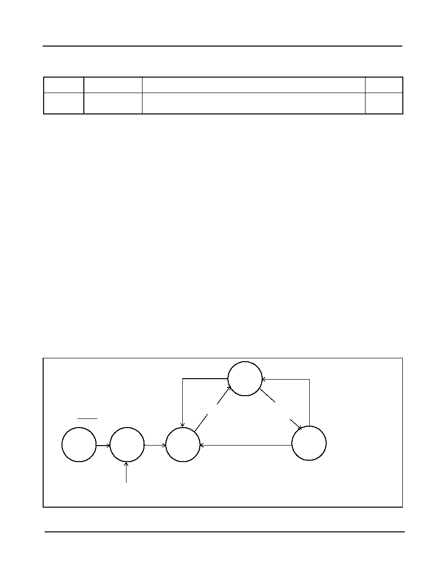
System Start-up Sequence: FREE-RUN --> HOLDOVER --> NORMAL
The FREE-RUN to HOLDOVER to NORMAL transition represents a sequence of steps that will most likely occur
during a new system installation or scheduled maintenance of timing cards. The process starts from the RESET
state and then transitions to Free-run mode where the system (card) is being initialized. At the end of this process
the ZL30402 should be switched into Normal mode (with MS2, MS1 set to 00) instead of Holdover mode. If the
reference clock is available, the ZL30402 will transition briefly into Holdover to acquire synchronization and switch
automatically to Normal mode. If the reference clock is not available at this time, as it may happen during new
system installation, then the ZL30402 will stay in Holdover indefinitely. While in Holdover mode, the Core PLL will
continue generating clocks with the same accuracy as in the Free-run mode, waiting for a good reference clock.
When the system is connected to the network (or timing card switched to a valid reference) the Acquisition PLL will
quickly synchronize and clear its own Holdover status (PAH bit). This will enable the Core PLL to start the
synchronization process. After acquiring lock, the ZL30402 will automatically switch from Holdover into Normal
mode without system intervention. This transition to the Normal mode will be flagged by the LOCK status bit and
pin.
Figure 7 - Transition from Free-Run to Normal Mode
Bit
Name
Functional Description
Default
7-0
MCFC7 - 0
Master Clock Frequency Calibration. This byte contains bit 7 to
bit 0 of the Master Clock Frequency Calibration Register.
00000
000
Table 21 - Master Clock Frequency Calibration Register 1 (R/W)
NORMAL
(LOCKED)
00
AUTO
HOLD-
OVER
HOLD-
OVER
01
FREE-
RUN
10
RESET
Ref: OK &
MS2, MS1 == 00
{AUTO}
Ref: OK --> FAIL &
MS2, MS1 == 00
{AUTO}
MS2, MS1 == 01 OR
RefSel change
Ref: FAIL --> OK &
MS2, MS1 == 00 &
AHRD=1 &
MHR= 0 -->1 then 1-->0
{MANUAL}
Ref: FAIL --> OK &
MS2, MS1 == 00 &
AHRD=0
{AUTO}
MS2, MS1 == 10 forces
unconditional return from
any state to Free-run
MS2, MS1! = 10
RESET == 1
RefSel Change
相關(guān)PDF資料 |
PDF描述 |
|---|---|
| ZL50112GAG2 | SPECIALTY TELECOM CIRCUIT, PBGA552 |
| ZL50112GAG | SPECIALTY TELECOM CIRCUIT, PBGA552 |
| ZL50114GAG2 | SPECIALTY TELECOM CIRCUIT, PBGA552 |
| ZL50114GAG | SPECIALTY TELECOM CIRCUIT, PBGA552 |
| ZL50232GD | DATACOM, ISDN ECHO CANCELLER, PBGA208 |
相關(guān)代理商/技術(shù)參數(shù) |
參數(shù)描述 |
|---|---|
| ZL30406 | 制造商:ZARLINK 制造商全稱(chēng):Zarlink Semiconductor Inc 功能描述:SONET/SDH Clock Multiplier PLL |
| ZL30406_06 | 制造商:ZARLINK 制造商全稱(chēng):Zarlink Semiconductor Inc 功能描述:SONET/SDH Clock Multiplier PLL |
| ZL30406QGC | 制造商:Zarlink Semiconductor Inc 功能描述:PLL CLOCK MLTPLR SGL UP TO 19.44MHZ 64TQFP - Trays |
| ZL30406QGC1 | 制造商:ZARLINK 制造商全稱(chēng):Zarlink Semiconductor Inc 功能描述:SONET/SDH Clock Multiplier PLL |
| ZL30406QGG1 | 制造商:Microsemi Corporation 功能描述:IC PB FREE T1/E1 SYS. SYNC+STRATUM 3 H/O 制造商:Microsemi Corporation 功能描述:PB FREE SONET/SDH CLOCK MULTIPLIER PLL - Trays 制造商:MICROSEMI CONSUMER MEDICAL PRODUCT GROUP 功能描述:IC PLL SONET/SDH CLK MULT 64TQFP 制造商:Microsemi Corporation 功能描述:IC PLL SONET/SDH CLK MULT 64TQFP |
發(fā)布緊急采購(gòu),3分鐘左右您將得到回復(fù)。