- 您現(xiàn)在的位置:買(mǎi)賣(mài)IC網(wǎng) > PDF目錄368967 > 29F800 (Fujitsu Limited) 8M (1M X 8/512K X 16) BIT PDF資料下載
參數(shù)資料
| 型號(hào): | 29F800 |
| 廠商: | Fujitsu Limited |
| 英文描述: | 8M (1M X 8/512K X 16) BIT |
| 中文描述: | 800萬(wàn)(100萬(wàn)X 8/512K × 16)位 |
| 文件頁(yè)數(shù): | 9/21頁(yè) |
| 文件大小: | 142K |
| 代理商: | 29F800 |
第1頁(yè)第2頁(yè)第3頁(yè)第4頁(yè)第5頁(yè)第6頁(yè)第7頁(yè)第8頁(yè)當(dāng)前第9頁(yè)第10頁(yè)第11頁(yè)第12頁(yè)第13頁(yè)第14頁(yè)第15頁(yè)第16頁(yè)第17頁(yè)第18頁(yè)第19頁(yè)第20頁(yè)第21頁(yè)
9/21
M29F800AT, M29F800AB
The Program/Erase Controller will suspend within
15
μ
s of the Erase Suspend Command being is-
sued. Once the Program/Erase Controller has
stopped the memory willbe set to Read mode and
the Erasewill be suspended. If the Erase Suspend
command is issued during the period when the
memory is waiting for an additional block (before
the Program/Erase Controller starts) then the
Erase is suspended immediately and will start im-
mediately when the Erase Resume Command is
issued. It will not be possible to select any further
blocks for erasure after the Erase Resume.
During Erase Suspend it is possible to Read and
Program cells in blocks that are not being erased;
both Read and Program operations behave as
normal on these blocks. Reading from blocks that
are being erased will output the Status Register. It
is alsopossible to enter theAuto Select mode: the
memory willbehave as inthe Auto Select mode on
all blocks until a Read/Resetcommand returns the
memory to Erase Suspend mode.
Erase Resume Command.
The Erase Resume
command must be used to restart the Program/
Erase Controller from Erase Suspend. An erase
can be suspended and resumed more than once.
STATUS REGISTER
Bus Read operations from any address always
read the Status Register during Program and
Erase operations. It isalso readduring EraseSus-
pend when an address within a block being erased
is accessed.
The bits in the Status Register are summarized in
Table 7, Status Register Bits.
Data Polling Bit (DQ7).
The Data Polling Bit can
be used to identify whether the Program/Erase
Controller has successfully completed its opera-
tion or if it has responded to an Erase Suspend.
The Data Polling Bit is output on DQ7 when the
Status Register is read.
During Program operations the Data Polling Bit
outputs the complement of the bit being pro-
grammed to DQ7. After successful completion of
the Program operation the memory returns to
Read mode and Bus Read operations from the ad-
dress just programmed output DQ7, not its com-
plement.
During Erase operations the Data Polling Bit out-
puts ’0’, the complement of the erased state of
DQ7. After successful completion of the Erase op-
eration the memory returns to Read Mode.
In Erase Suspend mode the Data Polling Bit will
output a ’1’ during a Bus Read operation within a
block being erased. The Data Polling Bit will
change from a ’0’ to a ’1’ when the Program/Erase
Controller has suspended the Erase operation.
Figure 3, Data Polling Flowchart, gives an exam-
ple of how to use the Data Polling Bit. A Valid Ad-
dress is the address being programmed or an
address within the block being erased.
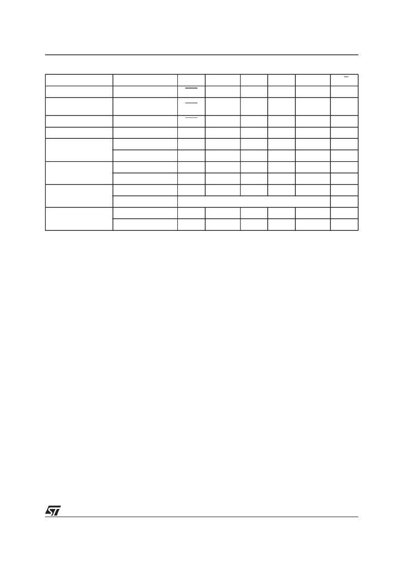
Table 7. Status Register Bits
Note: Unspecified data bits should be ignored.
Operation
Address
DQ7
DQ6
DQ5
DQ3
DQ2
RB
Program
Any Address
DQ7
Toggle
0
–
–
0
Program During Erase
Suspend
Any Address
DQ7
Toggle
0
–
–
0
Program Error
Any Address
DQ7
Toggle
1
–
–
0
Chip Erase
Any Address
0
Toggle
0
1
Toggle
0
Block Erase before
timeout
Erasing Block
0
Toggle
0
0
Toggle
0
Non-Erasing Block
0
Toggle
0
0
No Toggle
0
Block Erase
Erasing Block
0
Toggle
0
1
Toggle
0
Non-Erasing Block
0
Toggle
0
1
No Toggle
0
Erase Suspend
Erasing Block
1
No Toggle
0
1
Toggle
1
Non-Erasing Block
Data read as normal
1
Erase Error
Good Block Address
0
Toggle
1
1
No Toggle
0
Faulty Block Address
0
Toggle
1
1
Toggle
0
相關(guān)PDF資料 |
PDF描述 |
|---|---|
| 29F800 | 8 Megabit (1 M x 8-Bit/512 K x 16-Bit) CMOS 5.0 Volt-only, Boot Sector Flash Memory-Die Revision 1 |
| 29K_JTAG | 5-Pin, Multiple-Input, Programmable Reset ICs |
| 29K_PERIPH | on an Am29030 Microprocessor Design Using Slow Peripherals with 29K Family Processors |
| 29K_RESET | 5-Pin, Multiple-Input, Programmable Reset ICs |
| 29K_SUPMODE | Am29030 and Am29035 Microprocessors Defining a Trap to Switch to Supervisor Mode |
相關(guān)代理商/技術(shù)參數(shù) |
參數(shù)描述 |
|---|---|
| 29F800BT90SI | 制造商: 功能描述: 制造商:undefined 功能描述: |
| 29F800DT-70N1 | 制造商:undefined 功能描述: |
| 29FCT2052CTQG | 制造商:Integrated Device Technology Inc 功能描述:OCTAL REGISTR TRANSCEIVER - Tape and Reel |
| 29FCT2052HCTQ | 制造商:Integrated Device Technology Inc 功能描述: |
| 29FCT520ASO | 制造商:Integrated Device Technology Inc 功能描述:PIPELINE REGISTER MULTILEVEL |
發(fā)布緊急采購(gòu),3分鐘左右您將得到回復(fù)。