- 您現(xiàn)在的位置:買賣IC網(wǎng) > PDF目錄36337 > 935261351112 (NXP SEMICONDUCTORS) COLOR SIGNAL DECODER, PDIP32 PDF資料下載
參數(shù)資料
| 型號: | 935261351112 |
| 廠商: | NXP SEMICONDUCTORS |
| 元件分類: | 顏色信號轉(zhuǎn)換 |
| 英文描述: | COLOR SIGNAL DECODER, PDIP32 |
| 封裝: | 0.400 INCH, PLASTIC, SOT-232, SDIP-32 |
| 文件頁數(shù): | 45/47頁 |
| 文件大?。?/td> | 390K |
| 代理商: | 935261351112 |
第1頁第2頁第3頁第4頁第5頁第6頁第7頁第8頁第9頁第10頁第11頁第12頁第13頁第14頁第15頁第16頁第17頁第18頁第19頁第20頁第21頁第22頁第23頁第24頁第25頁第26頁第27頁第28頁第29頁第30頁第31頁第32頁第33頁第34頁第35頁第36頁第37頁第38頁第39頁第40頁第41頁第42頁第43頁第44頁當前第45頁第46頁第47頁

1996 Jan 17
7
Philips Semiconductors
Preliminary specication
I2C-bus controlled, alignment-free PAL/NTSC/SECAM
decoder/sync processor with PALplus helper demodulator
TDA9144
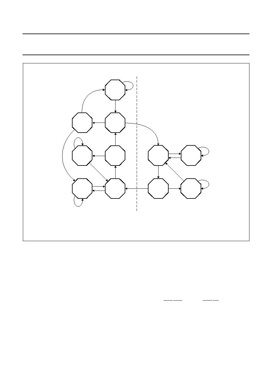
Fig.3 Search loop of the identification circuit.
handbook, full pagewidth
PAL
KILLED
PAL
KILLED
PAL
KILLED
NTSC
KILLED
NTSC
KILLED
SECAM
KILLED
Reference crystal
Second crystal
MGE040
PAL
NTSC
PAL
SECAM
c
Integrated lters
All chrominance bandpass and notch filters, including the
luminance delay line, are an integral part of the IC. The
filters are gyrator-capacitor type filters. The resonant
frequency of the filters is controlled by a circuit that uses
the active crystal to tune the SECAM Cloche filter during
the vertical flyback time. The remaining filters and the
luminance delay line are matched to this filter. The filters
can be switched to either 4.43 MHz, 4.29 MHz or
3.58 MHz. The switching is controlled by the standard
identification circuit. The luminance notch used for
SECAM has a lower Q-factor than the notch used for
PAL/NTSC. The notches are provided with a little preshoot
to obtain a symmetrical step response. In Y/C mode the
chrominance notch filters are bypassed, to preserve full
signal bandwidth. For a CVBS signal the chrominance
notch filters can be bypassed by bus selection of bit TB
(trap bypass).
The luminance to helper delay difference can be adjusted
by I2C-bus, to achieve a correct fitting for the delay in the
PALplus helper demodulation signal path and the
luminance path (not for helper only with trap). The delay of
the colour difference signals
(RY) and (BY) in the
chrominance signal path and the external chrominance
delay lines when used, can be fitted to the luminance
signal delay control via I2C-bus in 40 ns steps.
The typical luminance delay can be calculated:
delay
≈ 90 + SAKSBK {170 + 40(FRQTB)} + 160(YD3) +
160(YD2) + 80(YD1) + 40(YD0) [ns].
相關(guān)PDF資料 |
PDF描述 |
|---|---|
| 935261504518 | SPECIALTY CONSUMER CIRCUIT, PQFP44 |
| 935261504551 | SPECIALTY CONSUMER CIRCUIT, PQFP44 |
| 935261504557 | SPECIALTY CONSUMER CIRCUIT, PQFP44 |
| 935261537118 | DELTA-SIGMA ADC, PDSO16 |
| 935261537112 | DELTA-SIGMA ADC, PDSO16 |
相關(guān)代理商/技術(shù)參數(shù) |
參數(shù)描述 |
|---|---|
| 935262025112 | 制造商:NXP Semiconductors 功能描述:SUB ONLY IC |
| 935262217118 | 制造商:NXP Semiconductors 功能描述:Real Time Clock Serial 8-Pin SO T/R |
| 935264217557 | 制造商:NXP Semiconductors 功能描述:SUB ONLY IC |
| 935267356112 | 制造商:NXP Semiconductors 功能描述:IC TEA1507PN |
| 935268081112 | 制造商:NXP Semiconductors 功能描述:SUB ONLY IC |
發(fā)布緊急采購,3分鐘左右您將得到回復(fù)。