- 您現(xiàn)在的位置:買賣IC網(wǎng) > PDF目錄2064 > ADAV4601BSTZ (Analog Devices Inc)IC AUDIO CODEC PROCESSOR 80-LQFP PDF資料下載
參數(shù)資料
| 型號(hào): | ADAV4601BSTZ |
| 廠商: | Analog Devices Inc |
| 文件頁數(shù): | 15/60頁 |
| 文件大小: | 0K |
| 描述: | IC AUDIO CODEC PROCESSOR 80-LQFP |
| 標(biāo)準(zhǔn)包裝: | 1 |
| 系列: | SigmaDSP® |
| 類型: | 音頻處理器 |
| 應(yīng)用: | TV |
| 安裝類型: | 表面貼裝 |
| 封裝/外殼: | 80-LQFP |
| 供應(yīng)商設(shè)備封裝: | 80-LQFP(14x14) |
| 包裝: | 托盤 |
第1頁第2頁第3頁第4頁第5頁第6頁第7頁第8頁第9頁第10頁第11頁第12頁第13頁第14頁當(dāng)前第15頁第16頁第17頁第18頁第19頁第20頁第21頁第22頁第23頁第24頁第25頁第26頁第27頁第28頁第29頁第30頁第31頁第32頁第33頁第34頁第35頁第36頁第37頁第38頁第39頁第40頁第41頁第42頁第43頁第44頁第45頁第46頁第47頁第48頁第49頁第50頁第51頁第52頁第53頁第54頁第55頁第56頁第57頁第58頁第59頁第60頁

ADAV4601
Rev. B | Page 22 of 60
DAC VOLTAGE OUTPUTS
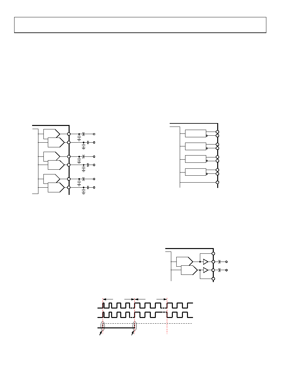
The ADAV4601 has six DAC outputs, configured as 3-stereo
auxiliary DAC outputs. However, because the flow is customizable,
it is programmable. The output level is 1 V rms full scale. The DAC
outputs should have a 10 nF capacitor to ground for filtering out
high frequency noise. Following the filtering capacitor, a 10 μF
is required for dc blocking.
After reset, the DACs are in a power-down state. They can power
up quickly using the global power-up in the initialization control
register (0x0000). A popless and clickless power-up and power-
down are also possible.
In power critical applications, it is possible to use the Analog
Power Management 1 register (0x0005) to power up or power
down individual DACs.
AUXOUT1L
AUXOUT1R
AUXOUT3L
AUXOUT3R
AUXOUT4L
AUXOUT4R
+
10F
10nF
+
10F
10nF
DAC
+
10F
10nF
+
10F
10nF
DAC
+
10F
10nF
+
10F
10nF
DAC
07
0-
1
04
Figure 30. DAC Output Section
PWM OUTPUTS
In the ADAV4601, the main outputs are available as four PWM
output channels, which are suitable for driving Class-D amplifiers.
After reset, the PWM channels are in a power-down state. Writing
to the miscellaneous control register (0x000A) enables the PWM
channels. To help ensure popless and clickless power-up and
power-down, there is an enable/disable pattern that is specially
constructed to bring the PWM channels from a zero condition
to a 50/50 duty-cycle square wave (effectively, a zero signal into
the PWM block). This takes 365 ms to complete and can be seen in
Designed for use in conjunction with this ramp-up scheme, the
ADAV4601 features a status pin, PWM_READY, that indicates
when the PWM outputs are in a state that can cause pops/clicks,
such as power-up and power-down. During PWM power-up
and power-down, this pin remains low to signify that the
outputs are not in a valid state. This functionality helps to
eliminate pop/click and other unwanted noise on the outputs.
To accommodate different power stages, the point at which the
PWM_READY signal goes high is programmable. It can go
high when the PWM outputs begin their ramp-up scheme
(PWM_READY early), or it can be programmed to go high
when this ramp-up scheme is complete (PWM_READY late).
This is shown in Figure 33, and it is configured in the PWM
control register (0x001F).
Each set of PWM outputs comprises complementary outputs.
The modulation frequency is 384 kHz, and the full-scale duty
cycle has a ratio of 97:3.
07
0-
0
25
PWM1A
PWM1B
PWM2A
PWM2B
PWM3A
PWM3B
PWM
MODULATOR
PWM
MODULATOR
PWM
MODULATOR
+
–
+
–
+
–
PWM4A
PWM_READY
PWM4B
PWM
MODULATOR
+
–
Figure 31. PWM Output Section
HEADPHONE OUTPUT
There is a dedicated stereo headphone amplifier output that is
capable of driving 32 Ω loads at 1 V rms.
After reset, the headphone output is tristated. The tristate is
disabled using the headphone control register (0x000B). Using
the same register, the gain of the headphone amplifier can be set in
+1.5 dB steps from +1.5 dB to 45 dB. The headphone output
should have a 10 μF capacitor for dc blocking.
HPOUT1L
AUXOUT4L
AUXOUT4R
HPOUT1R
+
10F
+
10F
DAC
PA
07
070
-10
6
Figure 32. Headphone Output Section
PWM1A
PWM1B
PWM READY
PWM READY EARLY
PWM READY LATE
DIFFERENTIAL PWM
IN PHASE
DIFFERENTIAL PWM
OUT OF PHASE—
VALID AUDIO
365ms
206s
0
707
0-
1
05
Figure 33. PWM Early
相關(guān)PDF資料 |
PDF描述 |
|---|---|
| ADAV4622BSTZ | IC AUD PRO ATV/SIF DECODE 80LQFP |
| ADCLK846BCPZ-REEL7 | IC CLK BUFFER 1:6 1.2GHZ 24LFCSP |
| ADCLK854BCPZ | IC CLOCK BUFFER MUX 2:12 48LFCSP |
| ADCLK907BCPZ-WP | IC CLK/DATA BUFF DVR 1:1 16LFCSP |
| ADCLK914BCPZ-WP | IC CLK/DATA BUFF DVR 1:1 16LFCSP |
相關(guān)代理商/技術(shù)參數(shù) |
參數(shù)描述 |
|---|---|
| ADAV4622 | 制造商:AD 制造商全稱:Analog Devices 功能描述:Audio Processor for Advanced TV with Sound IF Demodulator and Stereo Decoder |
| ADAV4622BSTZ | 功能描述:IC AUD PRO ATV/SIF DECODE 80LQFP RoHS:是 類別:集成電路 (IC) >> 線性 - 音頻處理 系列:SigmaDSP® 其它有關(guān)文件:STA321 View All Specifications 標(biāo)準(zhǔn)包裝:1 系列:Sound Terminal™ 類型:音頻處理器 應(yīng)用:數(shù)字音頻 安裝類型:表面貼裝 封裝/外殼:64-LQFP 裸露焊盤 供應(yīng)商設(shè)備封裝:64-LQFP EP(10x10) 包裝:Digi-Reel® 其它名稱:497-11050-6 |
| ADAV4-KIT-1 | 制造商:Wiebetech 功能描述:Combo Dock Kit #1 for Weibetech Ultradock Series |
| ADAV801 | 制造商:AD 制造商全稱:Analog Devices 功能描述:Audio Codec for Recordable DVD |
| ADAV801AST | 制造商:Analog Devices 功能描述:AUDIO CODEC FOR RECORDABLE DVD - Bulk |
發(fā)布緊急采購(gòu),3分鐘左右您將得到回復(fù)。