- 您現(xiàn)在的位置:買(mǎi)賣(mài)IC網(wǎng) > PDF目錄378445 > CH5101A (Electronic Theatre Controls, Inc.) CMOS Monochrome Digital Video Camera PDF資料下載
參數(shù)資料
| 型號(hào): | CH5101A |
| 廠商: | Electronic Theatre Controls, Inc. |
| 英文描述: | CMOS Monochrome Digital Video Camera |
| 中文描述: | 單色的CMOS數(shù)碼攝像機(jī) |
| 文件頁(yè)數(shù): | 25/32頁(yè) |
| 文件大小: | 132K |
| 代理商: | CH5101A |
第1頁(yè)第2頁(yè)第3頁(yè)第4頁(yè)第5頁(yè)第6頁(yè)第7頁(yè)第8頁(yè)第9頁(yè)第10頁(yè)第11頁(yè)第12頁(yè)第13頁(yè)第14頁(yè)第15頁(yè)第16頁(yè)第17頁(yè)第18頁(yè)第19頁(yè)第20頁(yè)第21頁(yè)第22頁(yè)第23頁(yè)第24頁(yè)當(dāng)前第25頁(yè)第26頁(yè)第27頁(yè)第28頁(yè)第29頁(yè)第30頁(yè)第31頁(yè)第32頁(yè)
CHRONTEL
CH5101A
201-0000-033 Rev 1.0, 6/2/99
25
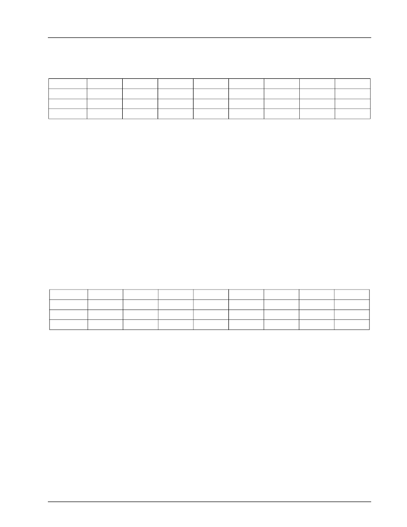
Auto-Shutter Enable
Symbol:ASE
Address:1Dh
Bits:8
Bits 0-2 of the ASE register control the speed of the autoshutter loop. Values 0 through 4 are valid.
Bits 3 - 4 of the ASE register are reserved, and should be left at their default value.
Bit 5 of the ASE register enables the autoshutter algorithm to adjust the gain of the programmable sample and hold.
A 1 in this location allows the autoshutter algorithm to control this gain. A zero in this location disables the
autoshutter algorithm from controlling this value, and allows bits 2-0 of register PSHG (17H) to control the gain.
Bit 6 of the ASE register enables the autoshutter algorithm to adjust the black level (bias) of the readout signal prior
to A/D conversion. A 1 in this location allows the autoshutter algorithm to control the black level. A 0 in this
location disables the autoshutter algorithm from controlling this value and allows bits 7-0 of register BCLMP (18H)
to control the black level.
Bit 7 of the ASE register enables the autoshutter algorithm to adjust the shutter duration. A 1 in this location allows
the autoshutter algorithm to control the shutter. A zero in this location disables the autoshutter algorithm from
controlling this value and allows registers ESLE, ESLH and ESLL to control the shutter duration.
Auto-Shutter Window / Input Control
Symbol:ASW
Address:1Eh
Bits:7
Bits 0, 1, 2 and 3 of the ASW register determine the active window that is used to operate the autoshutter algorithm.
There are 16 possible windows, which are shown in
Figure 12.
The default value of these bits can be set using the
PUD [3:0] inputs. This allows the backlight compensation window to be set without using IIC control.
Bit 4 of the ASW register enables the selected window to be highlighted in the image which is output from the
CH5101. All image outside of the window will be reduced in amplitude.
Bits 5 and 6 of the ASW register determine which data is input to the autoshutter algorithm, according to
Table 12
.
BIT:
7
6
5
4
3
2
1
0
SYMBOL:
TYPE:
ASSE
ASBE
ASGE
Reserved
Reserved
ASSPD2
ASSPD1
ASSPD0
R/W
R/W
R/W
R/W
R/W
R/W
R/W
R/W
DEFAULT:
1
1
1
0
0
1
0
0
BIT:
7
6
5
4
3
2
1
0
SYMBOL:
TYPE:
ASME
ASCSC
ASWD
ASW3
ASW2
ASW1
ASW0
R/W
R/W
R/W
R/W
R/W
R/W
R/W
DEFAULT:
1
0
0
PUD3*
PUD2*
PUD1*
PUD0*
相關(guān)PDF資料 |
PDF描述 |
|---|---|
| CH5101A-L | CMOS Monochrome Digital Video Camera |
| CH7003B-T | Digital PC to TV Encoder |
| CH7003B | Digital PC to TV Encoder |
| CH7003B-V | Digital PC to TV Encoder |
| CH7006C | MODULE |
相關(guān)代理商/技術(shù)參數(shù) |
參數(shù)描述 |
|---|---|
| CH5101A-L | 制造商:未知廠家 制造商全稱(chēng):未知廠家 功能描述:CMOS Monochrome Digital Video Camera |
| CH5101A-Q | 制造商:未知廠家 制造商全稱(chēng):未知廠家 功能描述:CMOS Monochrome Digital Video Camera |
| CH511H-30PT | 制造商:CHENMKO 制造商全稱(chēng):Chenmko Enterprise Co. Ltd. 功能描述:SCHOTTKY BARRIER DIODE VOLTAGE 30 Volts CURRENT 1.0 Ampere |
| CH511H-40PT | 制造商:CHENMKO 制造商全稱(chēng):Chenmko Enterprise Co. Ltd. 功能描述:SCHOTTKY BARRIER DIODE VOLTAGE 40 Volts CURRENT 1.0 Ampere |
| CH5125C6W | 制造商:Cooper Crouse-Hinds 功能描述: |
發(fā)布緊急采購(gòu),3分鐘左右您將得到回復(fù)。