- 您現(xiàn)在的位置:買賣IC網(wǎng) > PDF目錄26509 > CS2100P-DZZR (CIRRUS LOGIC INC) PDF資料下載
參數(shù)資料
| 型號(hào): | CS2100P-DZZR |
| 廠商: | CIRRUS LOGIC INC |
| 元件分類: | PLL合成/DDS/VCOs |
| 中文描述: | PHASE LOCKED LOOP, 30 MHz, PDSO10 |
| 封裝: | 3 MM, LEAD FREE, MO-187, MSOP-10 |
| 文件頁(yè)數(shù): | 8/25頁(yè) |
| 文件大小: | 223K |
| 代理商: | CS2100P-DZZR |
第1頁(yè)第2頁(yè)第3頁(yè)第4頁(yè)第5頁(yè)第6頁(yè)第7頁(yè)當(dāng)前第8頁(yè)第9頁(yè)第10頁(yè)第11頁(yè)第12頁(yè)第13頁(yè)第14頁(yè)第15頁(yè)第16頁(yè)第17頁(yè)第18頁(yè)第19頁(yè)第20頁(yè)第21頁(yè)第22頁(yè)第23頁(yè)第24頁(yè)第25頁(yè)
CS2100-OTP
16
DS841F2
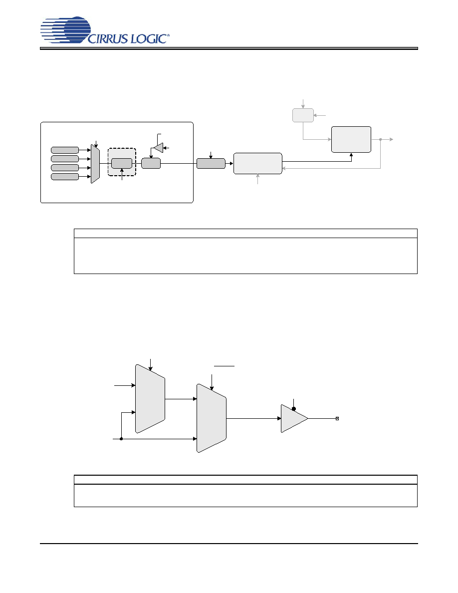
final calculation used to determine the output to input clock ratio. The effective ratio is then corrected for
the internal dividers. The conceptual diagram in Figure 12 summarizes the features involved in the calcu-
lation of the ratio values used to generate the fractional-N value which controls the Frequency Synthesiz-
er. The subscript ‘4’ indicates the modal parameters.
Figure 12. Ratio Feature Summary
5.5
PLL Clock Output
The PLL clock output pin (CLK_OUT) provides a buffered version of the output of the frequency synthesizer.
The driver can be set to high-impedance with the M2 pin when the M2Config[1:0] global parameter is set to
either 000 or 010. The output from the PLL automatically drives a static low condition while the PLL is un-
locked (when the clock may be unreliable). This feature can be disabled by setting the ClkOutUnl global
parameter, however the state CLK_OUT may then be unreliable during an unlock condition.
Figure 13. PLL Clock Output Options
Referenced Control
Parameter Definition
Ratio 0-3................................“Ratio 0 - 3” on page 21
M[1:0] pins............................. “M1 and M0 Mode Pin Functionality” on page 17
LFRatioCfg ............................ “Low-Frequency Ratio Configuration (LFRatioCfg)” on page 22
RModSel[1:0] ........................ “R-Mod Selection (RModSel[1:0])” section on page 20
RefClkDiv[1:0] ....................... “Reference Clock Input Divider (RefClkDiv[1:0])” on page 21
Referenced Control
Parameter Definition
ClkOutUnl.............................. “Enable PLL Clock Output on Unlock (ClkOutUnl)” on page 22
ClkOutDis .............................. “M2 Configured as Output Disable” on page 18
M2Config[2:0]........................“M2 Pin Configuration (M2Config[2:0])” on page 22
Effective Ratio REFF
Ratio Format
Frequency Reference Clock
(CLK_IN)
SysClk
PLL Output
Frequency
Synthesizer
Digital PLL &
Fractional N Logic
Ratio 0
Ratio 1
Ratio 2
Ratio 3
12.20
20.12
M[1:0] pins
LFRatioCfg
RModSel[1:0]4
Ratio
Modifier
R Correction
RefClkDiv[1:0]
Timing Reference Clock
(XTI/REF_CLK)
Divide
RefClkDiv[1:0]
Dynamic Ratio, ‘N’
User Defined Ratio RUD
M2 pin
PLL Locked/Unlocked
PLL Output
2:1 Mux
M2 pin with
M2Config[1:0] = 000, 010
2:1 Mux
ClkOutUnl
0
PLL Clock Output Pin
(CLK_OUT)
0
1
0
1
PLL Clock Output
PLLClkOut
相關(guān)PDF資料 |
PDF描述 |
|---|---|
| CS2200P-DZZR | |
| CS2300P-DZZR | |
| CS3511-CNZR | |
| CS35L00-CNZ | |
| CS4207-DNZR | |
相關(guān)代理商/技術(shù)參數(shù) |
參數(shù)描述 |
|---|---|
| CS2106 | 制造商:Coilcraft Inc 功能描述:NOT RoHS. Current sense transformer (add 'L' for compliant version) |
| CS2106L | 制造商:Coilcraft Inc 功能描述:Current sense transformer, RoHS |
| CS2113-1 | 制造商:Edwards Signaling & Security Systems 功能描述:BELL 432-115V60HZ OTIS |
| CS2113-10 | 制造商:Edwards Signaling & Security Systems 功能描述:GONG |
| CS2113-2 | 制造商:Edwards Signaling & Security Systems 功能描述:BELL 432 115V60AZ OTIS |
發(fā)布緊急采購(gòu),3分鐘左右您將得到回復(fù)。