- 您現(xiàn)在的位置:買(mǎi)賣(mài)IC網(wǎng) > PDF目錄378517 > CYV15G0201DXB (Cypress Semiconductor Corp.) Dual-channel HOTLink II Transceiver PDF資料下載
參數(shù)資料
| 型號(hào): | CYV15G0201DXB |
| 廠商: | Cypress Semiconductor Corp. |
| 英文描述: | Dual-channel HOTLink II Transceiver |
| 中文描述: | 雙通道HOTLink II收發(fā)器 |
| 文件頁(yè)數(shù): | 13/46頁(yè) |
| 文件大小: | 577K |
| 代理商: | CYV15G0201DXB |
第1頁(yè)第2頁(yè)第3頁(yè)第4頁(yè)第5頁(yè)第6頁(yè)第7頁(yè)第8頁(yè)第9頁(yè)第10頁(yè)第11頁(yè)第12頁(yè)當(dāng)前第13頁(yè)第14頁(yè)第15頁(yè)第16頁(yè)第17頁(yè)第18頁(yè)第19頁(yè)第20頁(yè)第21頁(yè)第22頁(yè)第23頁(yè)第24頁(yè)第25頁(yè)第26頁(yè)第27頁(yè)第28頁(yè)第29頁(yè)第30頁(yè)第31頁(yè)第32頁(yè)第33頁(yè)第34頁(yè)第35頁(yè)第36頁(yè)第37頁(yè)第38頁(yè)第39頁(yè)第40頁(yè)第41頁(yè)第42頁(yè)第43頁(yè)第44頁(yè)第45頁(yè)第46頁(yè)
CYP15G0201DXB
CYV15G0201DXB
Document #: 38-02058 Rev. *G
Page 13 of 46
Parity Support
In addition to the ten data and control bits that are captured at
each transmit Input Register, a TXOPx input is also available
on each channel. This allows the CYP(V)15G0201DXB to
support ODD parity checking for each channel. This parity
checking is available for all operating modes (including
Encoder Bypass). The specific mode of parity checking is
controlled by the PARCTL input, and operates per
Table 2
.
When PARCTL is MID (open) and the Encoders are enabled
(TXMODE[1]
≠
L), only the TXDx[7:0] data bits are checked for
ODD parity along with the associated TXOPx bit. When
PARCTL = HIGH with the Encoder enabled (or MID with the
Encoder bypassed), the TXDx[7:0] and TXCTx[1:0] inputs are
checked for ODD parity along with the associated TXOPx bit.
When PARCTL = LOW, parity checking is disabled.
When parity checking and the Encoder are both enabled
(TXMODE[1]
≠
LOW), the detection of a parity error causes a
C0.7 character of proper disparity to be passed to the Transmit
Shifter. When the Encoder is bypassed (TXMODE[1] = LOW),
detection of a parity error causes a positive disparity version
of a C0.7 transmission character to be passed to the Transmit
Shifter.
Encoder
The character, received from the Input Register or
Phase-Align Buffer and Parity Check logic, is then passed to
the Encoder logic. This block interprets each character and
any associated control bits, and outputs a 10-bit transmission
character.
Depending on the configured operating mode, the generated
transmission character may be
the 10-bit pre-encoded character accepted in the Input
Register
the 10-bit equivalent of the 8-bit Data character accepted in
the Input Register
the 10-bit equivalent of the 8-bit Special Character code
accepted in the Input Register
Notes:
8.
Transmit path parity errors are reported on the associated TXPERx output.
9.
Bits marked as X are XORed together. Result must be a logic-1 for parity to be valid.
the 10-bit equivalent of the C0.7 SVS character if parity
checking was enabled and a parity error was detected
the 10-bit equivalent of the C0.7 SVS character if a
Phase-Align Buffer overflow or underflow error is present
a character that is part of the 511-character BIST sequence
a K28.5 character generated as an individual character or
as part of the 16-character Word Sync Sequence.
The selection of the specific characters generated is controlled
by the TXMODE[1:0], SCSEL, TXCTx[1:0], and TXDx[7:0]
inputs for each character.
Data Encoding
Raw data, as received directly from the Transmit Input
Register, is seldom in a form suitable for transmission across
a serial link. The characters must usually be processed or
transformed to guarantee
a minimum transition density (to allow the serial receive PLL
to extract a clock from the data stream)
a DC-balance in the signaling (to prevent baseline wander)
run-length limits in the serial data (to limit the bandwidth
requirements of the serial link)
the remote receiver a way of determining the correct
character boundaries (framing).
When the Encoder is enabled (TXMODE[1]
≠
LOW), the
characters to be transmitted are converted from Data or
Special Character codes to 10-bit transmission characters (as
selected by their respective TXCTx[1:0] and SCSEL inputs),
using an integrated 8B/10B Encoder. When directed to encode
the character as a Special Character code, it is encoded using
the Special Character encoding rules listed in
Table 25
. When
directed to encode the character as a Data character, it is
encoded using the Data Character encoding rules in
Table 24
.
The 8B/10B Encoder is standards compliant with ANSI/NCITS
ASC X3.230-1994 (Fibre Channel), IEEE 802.3z (Gigabit
Ethernet), the IBM
ESCON
and FICON
channels, and
Digital Video Broadcast DVB-ASI standards for data transport.
Many of the Special Character codes listed in
Table 25
may be
generated by more than one input character. The
CYP(V)15G0201DXB is designed to support two independent
(but non-overlapping) Special Character code tables. This
allows the CYP(V)15G0201DXB to operate in mixed environ-
ments with other CYP(V)15G0201DXBs using the enhanced
Cypress command code set, and the reduced command sets
of other non-Cypress devices. Even when used in an
environment that normally uses non-Cypress Special
Character codes, the selective use of Cypress command
codes can permit operation where running disparity and error
handling must be managed.
Following conversion of each input character from eight bits to
a 10-bit transmission character, it is passed to the Transmit
Shifter and is shifted out LSB first, as required by ANSI and
IEEE standards for 8B/10B coded serial data streams.
Transmit Modes
The operating mode of the transmit path is set through the
TXMODE[1:0] inputs. These 3-level select inputs allow one of
nine transmit modes to be selected. The transmit modes are
listed in
Table 3
.
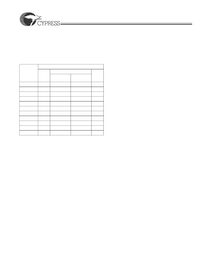
Table 2. Input Register Bits Checked for Parity
[8]
Signal
Name
TXDx[0]
TXDx[1]
TXDx[2]
TXDx[3]
TXDx[4]
TXDx[5]
TXDx[6]
TXDx[7]
TXCTx[0]
TXCTx[1]
TXOPx
Transmit Parity Check Mode (PARCTL)
MID
TXMODE[1]
= LOW
X
[9]
X
X
X
X
X
X
X
X
X
X
LOW
HIGH
X
X
X
X
X
X
X
X
X
X
X
TXMODE[1]
≠
LOW
X
X
X
X
X
X
X
X
X
相關(guān)PDF資料 |
PDF描述 |
|---|---|
| CYV15G0201DXB-BBC | Dual-channel HOTLink II Transceiver |
| CYV15G0404RB-BGC | Independent Clock Quad HOTLink Reclocking Deserializer |
| CYW15G0101DXB | Single-channel HOTLink II Transceiver(單通道熱連接II收發(fā)器) |
| CYW2315 | Serial Input PLL with 1.2-GHz Prescaler(帶1.2-GHz 預(yù)標(biāo)定器的串聯(lián)輸入PLL) |
| CYW2320 | Serial Input PLL with 2.0-GHz Prescaler(帶2.0-GHz 預(yù)標(biāo)定器的串聯(lián)輸入PLL) |
相關(guān)代理商/技術(shù)參數(shù) |
參數(shù)描述 |
|---|---|
| CYV15G0201DXB-BBC | 功能描述:電信線路管理 IC Dual Ch Video COM RoHS:否 制造商:STMicroelectronics 產(chǎn)品:PHY 接口類(lèi)型:UART 電源電壓-最大:18 V 電源電壓-最小:8 V 電源電流:30 mA 最大工作溫度:+ 85 C 最小工作溫度:- 40 C 安裝風(fēng)格:SMD/SMT 封裝 / 箱體:VFQFPN-48 封裝:Tray |
| CYV15G0201DXB-BBI | 制造商:Cypress Semiconductor 功能描述: |
| CYV15G0201DXB-BBXC | 功能描述:電信線路管理 IC Dual Ch Video COM RoHS:否 制造商:STMicroelectronics 產(chǎn)品:PHY 接口類(lèi)型:UART 電源電壓-最大:18 V 電源電壓-最小:8 V 電源電流:30 mA 最大工作溫度:+ 85 C 最小工作溫度:- 40 C 安裝風(fēng)格:SMD/SMT 封裝 / 箱體:VFQFPN-48 封裝:Tray |
| CYV15G0201DXB-BBXI | 功能描述:電信線路管理 IC Dual Ch Video IND RoHS:否 制造商:STMicroelectronics 產(chǎn)品:PHY 接口類(lèi)型:UART 電源電壓-最大:18 V 電源電壓-最小:8 V 電源電流:30 mA 最大工作溫度:+ 85 C 最小工作溫度:- 40 C 安裝風(fēng)格:SMD/SMT 封裝 / 箱體:VFQFPN-48 封裝:Tray |
| CYV15G0203TB | 制造商:CYPRESS 制造商全稱(chēng):Cypress Semiconductor 功能描述:Independent Clock Dual HOTLink II⑩ Serializer |
發(fā)布緊急采購(gòu),3分鐘左右您將得到回復(fù)。