- 您現(xiàn)在的位置:買賣IC網 > PDF目錄295864 > E0C88F360F 8-BIT, MROM, 8.2 MHz, MICROCONTROLLER, PQFP176 PDF資料下載
參數(shù)資料
| 型號: | E0C88F360F |
| 元件分類: | 微控制器/微處理器 |
| 英文描述: | 8-BIT, MROM, 8.2 MHz, MICROCONTROLLER, PQFP176 |
| 封裝: | PLASTIC, QFP18-176 |
| 文件頁數(shù): | 3/16頁 |
| 文件大?。?/td> | 120K |
| 代理商: | E0C88F360F |

11
E0C88F360
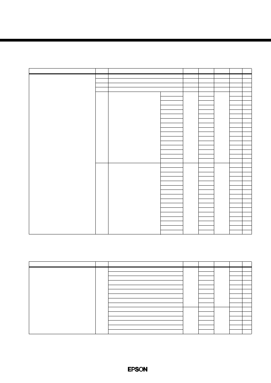
q Analog Circuit Characteristics
LCD drive circuit
LCD drive voltage
VC1
VC2
VC3
VC4
VC5
TYPE A
(4.5V)
VC5
TYPE B
(5.5V)
0.18VC5
0.39VC5
0.59VC5
0.80VC5
Typ
×0.94
Typ
×0.94
3.89
3.96
4.04
4.11
4.18
4.26
4.34
4.42
4.50
4.58
4.66
4.74
4.82
4.90
4.99
5.08
4.73
4.83
4.92
5.02
5.11
5.21
5.30
5.40
5.50
5.60
5.70
5.81
5.93
6.05
6.17
6.29
0.22VC5
0.43VC5
0.63VC5
0.84VC5
Typ
×1.06
Typ
×1.06
V
#1
#2
#3
#4
#5
LCX = 0H
LCX = 1H
LCX = 2H
LCX = 3H
LCX = 4H
LCX = 5H
LCX = 6H
LCX = 7H
LCX = 8H
LCX = 9H
LCX = AH
LCX = BH
LCX = CH
LCX = DH
LCX = EH
LCX = FH
LCX = 0H
LCX = 1H
LCX = 2H
LCX = 3H
LCX = 4H
LCX = 5H
LCX = 6H
LCX = 7H
LCX = 8H
LCX = 9H
LCX = AH
LCX = BH
LCX = CH
LCX = DH
LCX = EH
LCX = FH
Item
Symbol
Min.
Typ.
Max.
Unit
Condition
Note
#
1
#
2
#
3
(Unless otherwise specified: VDD=1.8 to 5.5V, VSS=0V, Ta=25
°C, C1–C9=0.1F)
Connects 1M
load resistor between VSS and VC1.
Connects 1M
load resistor between VSS and VC2.
Connects 1M
load resistor between VSS and VC3.
#
4
#
5
Connects 1M
load resistor between VSS and VC4.
Connects 1M
load resistor between VSS and VC5.
SVD circuit
Item
Symbol
Min.
Typ.
Max.
Unit
Condition
SVD voltage
VSVD
Typ
×0.92
Typ
×0.88
1.82
2.00
2.18
2.36
2.54
2.72
2.90
3.08
3.26
3.45
3.65
3.85
4.05
4.25
4.50
Typ
×1.08
Typ
×1.12
V
Level 1
→ Level 0
Level 2
→ Level 1
Level 3
→ Level 2
Level 4
→ Level 3
Level 5
→ Level 4
Level 6
→ Level 5
Level 7
→ Level 6
Level 8
→ Level 7
Level 9
→ Level 8
Level 10
→ Level 9
Level 11
→ Level 10
Level 12
→ Level 11
Level 13
→ Level 12
Level 14
→ Level 13
Level 15
→ Level 14
Note
6
7
8
Note)
VSVD (Level 0) < VSVD (Level 1) < VSVD (Level 2) < VSVD (Level 3) < VSVD (Level 4) < VSVD (Level 5) < VSVD (Level 6) < VSVD (Level 7) < VSVD (Level 8)
< VSVD (Level 9) < VSVD (Level 10) < VSVD (Level 11) < VSVD (Level 12) < VSVD (Level 13) < VSVD (Level 14) < VSVD (Level 15)
6
7
8
Low-power operation mode
Low-power or normal operation mode
Normal or high-speed operating mode
(Unless otherwise specified: VDD=1.8 to 5.5V, VSS=0V, Ta=25
°C)
相關PDF資料 |
PDF描述 |
|---|---|
| E112PD040D040SG | INTERCONNECTION DEVICE |
| E1SAA18-16.670MTR | QUARTZ CRYSTAL RESONATOR, 16.67 MHz |
| E1SAA18-3.686M | QUARTZ CRYSTAL RESONATOR, 3.686 MHz |
| E1SAD12-24.000MTR | QUARTZ CRYSTAL RESONATOR, 24 MHz |
| E1SAD18-33.3333MTR | QUARTZ CRYSTAL RESONATOR, 33.3333 MHz |
相關代理商/技術參數(shù) |
參數(shù)描述 |
|---|---|
| E0D2P7BP05T WAF | 制造商:ON Semiconductor 功能描述: |
| E0D3P9BP05T WAF | 制造商:ON Semiconductor 功能描述: |
| E0D4P3BP05T WAF | 制造商:ON Semiconductor 功能描述: |
| E0D4P7BP05T WAF | 制造商:ON Semiconductor 功能描述: |
| E0D5P6BP05TZ WAF | 制造商:ON Semiconductor 功能描述: |
發(fā)布緊急采購,3分鐘左右您將得到回復。