- 您現(xiàn)在的位置:買賣IC網(wǎng) > PDF目錄360859 > IMST425-J25S 32-Bit Microprocessor PDF資料下載
參數(shù)資料
| 型號: | IMST425-J25S |
| 元件分類: | 32位微控制器 |
| 英文描述: | 32-Bit Microprocessor |
| 中文描述: | 32位微處理器 |
| 文件頁數(shù): | 63/74頁 |
| 文件大?。?/td> | 563K |
| 代理商: | IMST425-J25S |
第1頁第2頁第3頁第4頁第5頁第6頁第7頁第8頁第9頁第10頁第11頁第12頁第13頁第14頁第15頁第16頁第17頁第18頁第19頁第20頁第21頁第22頁第23頁第24頁第25頁第26頁第27頁第28頁第29頁第30頁第31頁第32頁第33頁第34頁第35頁第36頁第37頁第38頁第39頁第40頁第41頁第42頁第43頁第44頁第45頁第46頁第47頁第48頁第49頁第50頁第51頁第52頁第53頁第54頁第55頁第56頁第57頁第58頁第59頁第60頁第61頁第62頁當(dāng)前第63頁第64頁第65頁第66頁第67頁第68頁第69頁第70頁第71頁第72頁第73頁第74頁
11 Transputer instruction set summary
/ 74
63
11.1.1
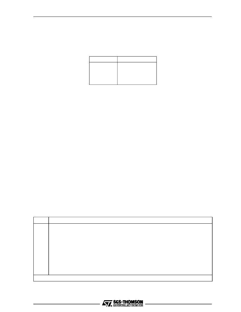
Product identity numbers
The loaddevice identity(lddevid) instruction (table 11.10)pushes thedevice typeidentityinto theAregis-
ter.Eachproductisallocatedauniquegroupofnumbersforusewiththelddevidinstruction.Productidenti-
ty numbers are given in table 11.3.
Product
IMS T425
IMS T805
IMS T225
IMS T400
Identity numbers
0 to 9 inclusive
10 to 19 inclusive
40 to 49 inclusive
50 to 59 inclusive
Table 11.3
Product identity numbers
11.1.2
Floating point unit
In the floating point unit (FPU) basic addition, subtraction, multiplication and division operations are per-
formedby singleinstructions.However,certain lessfrequentlyusedfloatingpointinstructionsareselected
by a value in registerA(when allocating registers, this shouldbe taken into account). A load constantin-
struction ldc is used to load register A the floating point entryinstruction fpentry then uses this value to
select the floating point operation. This pair of instructions is termed a selector sequence
In the Floating Point Operation Codes tables 11.23 to 11.29, a selector sequencecode is indicated in the
MemoryCodecolumnby
s
.ThecodegivenintheOperationCodecolumnistheindirectioncode,theoper-
and for the ldc instruction.
The FPUand processoroperateconcurrently, so theactualthroughput offloatingpoint instructionsis bet-
ter than that implied by simply adding up the instruction times. For full details see TransputerInstruction
Set – A Compiler Writer’s Guide
11.1.3
Notation
The Processor Cycles column refers to the number of periods
TPCLPCL
(refer to
ProcClockOut
) taken
by an instructionexecuting ininternal memory.The number of cycles is givenfor thebasic operationonly;
where the memory code for an instruction is two bytes, the time for theprefixfunction (one cycle) should
beadded.Someinstructiontimes vary.Where aletteris includedinthecyclescolumnitisinterpretedfrom
table 11.4.
Ident
b
m
Interpretation
Bit number of the highest bit set in register
A
. Bit 0 is the least significant bit.
Bit number of the highest bit set in the absolute value of register
A
. Bit 0 is the least signifi-
cant bit.
Number of places shifted.
Number of words in the message. Part words are counted as full words. If the message is not
word aligned the number of words is increased to include the part words at either end of the
message.
Number of words per row.
Number of rows.
does not apply to IMS T225
n
w
p
r
Table11.4
Instruction set interpretation
相關(guān)PDF資料 |
PDF描述 |
|---|---|
| IMST425-X25S | 32-Bit Microprocessor |
| IMST800C-G17S | Peripheral IC |
| IMST800C-G20S | Peripheral IC |
| IMST800C-G30S | Peripheral IC |
| IMST805-F20E | 32-Bit Microprocessor |
相關(guān)代理商/技術(shù)參數(shù) |
參數(shù)描述 |
|---|---|
| IMST425-X25S | 制造商:未知廠家 制造商全稱:未知廠家 功能描述:32-Bit Microprocessor |
| IMST800C-G17S | 制造商:未知廠家 制造商全稱:未知廠家 功能描述:Peripheral IC |
| IMST800C-G20S | 制造商:未知廠家 制造商全稱:未知廠家 功能描述:Peripheral IC |
| IMST800C-G30S | 制造商:未知廠家 制造商全稱:未知廠家 功能描述:Peripheral IC |
| IMST801 | 制造商:未知廠家 制造商全稱:未知廠家 功能描述:IMST801 TRANSPUETR |
發(fā)布緊急采購,3分鐘左右您將得到回復(fù)。