- 您現(xiàn)在的位置:買賣IC網(wǎng) > PDF目錄383118 > IRFP245 (HARRIS SEMICONDUCTOR) 15A and 14A, 275V and 250V, 0.28 and 0.34 Ohm, N-Channel Power MOSFETs PDF資料下載
參數(shù)資料
| 型號: | IRFP245 |
| 廠商: | HARRIS SEMICONDUCTOR |
| 元件分類: | 功率晶體管 |
| 英文描述: | 15A and 14A, 275V and 250V, 0.28 and 0.34 Ohm, N-Channel Power MOSFETs |
| 中文描述: | 14 A, 250 V, 0.34 ohm, N-CHANNEL, Si, POWER, MOSFET, TO-247 |
| 文件頁數(shù): | 2/7頁 |
| 文件大小: | 68K |
| 代理商: | IRFP245 |
5-2
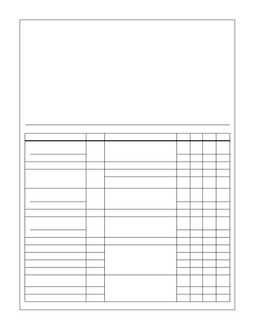
Absolute Maximum Ratings
T
C
= 25
o
C, Unless Otherwise Specified
IRFP244
250
250
15
9.7
60
±
20
150
1.2
550
-55 to 150
IRFP245
250
250
14
8.8
56
±
20
150
1.2
550
-55 to 150
IRFP246
275
275
15
9.7
60
±
20
150
1.2
550
-55 to 150
IRFP247
275
275
14
8.8
56
±
20
150
1.2
550
-55 to 150
UNITS
V
V
A
A
A
V
W
W/
o
C
mJ
o
C
Drain to Source Voltage (Note 1) . . . . . . . . . . . . . . . . . . . . . V
DS
Drain to Gate Voltage (R
GS
= 20k
)
(Note 1) . . . . . . . . . .V
DGR
Continuous Drain Current. . . . . . . . . . . . . . . . . . . . . . . . . . . . .I
D
T
C
= 100
o
C. . . . . . . . . . . . . . . . . . . . . . . . . . . . . . . . . . . . . .I
D
Pulsed Drain Current (Note 3) . . . . . . . . . . . . . . . . . . . . . . . I
DM
Gate to Source Voltage . . . . . . . . . . . . . . . . . . . . . . . . . . . . V
GS
Maximum Power Dissipation . . . . . . . . . . . . . . . . . . . . . . . . . P
D
Linear Derating Factor . . . . . . . . . . . . . . . . . . . . . . . . . . . . . .
Single Pulse Avalanche Energy Rating (Note 4) . . . . . . . . . E
AS
Operating and Storage Temperature . . . . . . . . . . . . . T
J
, T
STG
Maximum Temperature for Soldering
Leads at 0.063in (1.6mm) from Case for 10s . . . . . . . . . . . T
L
Package Body for 10s, See Techbrief 334 . . . . . . . . . . . .T
pkg
CAUTION: Stresses above those listed in “Absolute Maximum Ratings” may cause permanent damage to the device. This is a stress only rating and operation
of the device at these or any other conditions above those indicated in the operational sections of this specification is not implied.
300
260
300
260
300
260
300
260
o
C
o
C
NOTE:
1. T
J
= 25
o
C to 125
o
C.
Electrical Specifications
T
C
= 25
o
C, Unless Otherwise Specified
PARAMETER
SYMBOL
TEST CONDITIONS
MIN
TYP
MAX
UNITS
Drain to Source Breakdown Voltage
BV
DSS
V
GS
= 0V, I
D
= 250
μ
A (Figure 10)
IRFP244, IRFP245
250
-
-
V
IRFP246, IRFP247
275
-
-
V
Gate to Threshold Voltage
V
GS(TH)
V
GS
= V
DS
, I
D
= 250
μ
A
2.0
-
4.0
V
Zero-Gate Voltage Drain Current
I
DSS
V
DS
= Rated BV
DSS
, V
GS
= 0V
-
-
25
μ
A
V
DS
= 0.8 x Rated BV
DSS
, V
GS
= 0V
T
J
= 125
o
C
-
-
250
μ
A
On-State Drain Current (Note 2)
I
D(ON)
V
DS
> I
D(ON) x
r
DS(ON)MAX
, V
GS
= 10V
(Figure 7)
IRFP244, IRFP246
15
-
-
A
IRFP245, IRFP247
14
-
-
A
Gate to Source Leakage
I
GSS
V
GS
=
±
20V
-
-
±
100
nA
Drain to Source On Resistance (Note 2)
r
DS(ON)
V
GS
= 10V, I
D
= 10A (Figures 8, 9)
IRFP244, IRFP246
-
0.20
0.28
IRFP245, IRFP247
-
0.24
0.34
Forward Transconductance (Note 2)
g
fs
V
DS
≥
50V, I
D
= 10A (Figure 12)
6.7
11
-
S
Turn-On Delay Time
t
d(ON)
V
DD
= 125V, I
D
≈
15A, R
G
= 9.1
, V
GS
= 10V,
R
L
= 8
(Figures 17, 18) MOSFET Switching
Times are Essentially Independent of
Operating Temperature
-
16
24
ns
Rise Time
t
r
-
67
100
ns
Turn-Off Delay Time
t
d(OFF)
-
53
80
ns
Fall Time
t
f
-
49
74
ns
Total Gate Charge
(Gate to Source + Gate to Drain)
Q
g(TOT)
V
GS
= 10V, I
D
= 15A, V
DS
= 0.8 x Rated
BV
DSS
, I
G(REF)
= 1.5mA (Figures 14, 19, 20)
Gate charge is Essentially Independent of
Operating Temperature
-
39
59
nC
Gate to Source Charge
Q
gs
-
6.6
-
nC
Gate to Drain “Miller” Charge
Q
gd
-
20
-
nC
IRFP244, IRFP245, IRFP246, IRFP247
相關(guān)PDF資料 |
PDF描述 |
|---|---|
| IRFP246 | 15A and 14A, 275V and 250V, 0.28 and 0.34 Ohm, N-Channel Power MOSFETs |
| IRFP247 | 15A and 14A, 275V and 250V, 0.28 and 0.34 Ohm, N-Channel Power MOSFETs |
| IRFP250 | 33A, 200V, 0.085 Ohm,N-Channel PowerMOSFET(33A, 200V, 0.085 Ohm,N溝道增強(qiáng)型功率MOS場效應(yīng)管) |
| IRFP254 | Standard Power MOSFET - N-Channel Enhancement Mode |
| IRFP254 | Power MOSFET(Vdss = 250 V, Rds(on)=0.14ohm, Id=23A) |
相關(guān)代理商/技術(shù)參數(shù) |
參數(shù)描述 |
|---|---|
| IRFP246 | 制造商:Rochester Electronics LLC 功能描述:- Bulk |
| IRFP247 | 制造商:INTERSIL 制造商全稱:Intersil Corporation 功能描述:15A and 14A, 275V and 250V, 0.28 and 0.34 Ohm, N-Channel Power MOSFETs |
| IRFP250 | 功能描述:MOSFET N-Chan 200V 30 Amp RoHS:否 制造商:STMicroelectronics 晶體管極性:N-Channel 汲極/源極擊穿電壓:650 V 閘/源擊穿電壓:25 V 漏極連續(xù)電流:130 A 電阻汲極/源極 RDS(導(dǎo)通):0.014 Ohms 配置:Single 最大工作溫度: 安裝風(fēng)格:Through Hole 封裝 / 箱體:Max247 封裝:Tube |
| IRFP250_R4941 | 功能描述:MOSFET TO-247 N-Ch Power RoHS:否 制造商:STMicroelectronics 晶體管極性:N-Channel 汲極/源極擊穿電壓:650 V 閘/源擊穿電壓:25 V 漏極連續(xù)電流:130 A 電阻汲極/源極 RDS(導(dǎo)通):0.014 Ohms 配置:Single 最大工作溫度: 安裝風(fēng)格:Through Hole 封裝 / 箱體:Max247 封裝:Tube |
| IRFP250A | 制造商:FAIRCHILD 制造商全稱:Fairchild Semiconductor 功能描述:Advanced Power MOSFET |
發(fā)布緊急采購,3分鐘左右您將得到回復(fù)。