- 您現(xiàn)在的位置:買賣IC網(wǎng) > PDF目錄373177 > KS16112 (SAMSUNG SEMICONDUCTOR CO. LTD.) CAP 33PF 50V 5% NPO(C0G) SMD-0603 TR-7-PA PDF資料下載
參數(shù)資料
| 型號: | KS16112 |
| 廠商: | SAMSUNG SEMICONDUCTOR CO. LTD. |
| 英文描述: | CAP 33PF 50V 5% NPO(C0G) SMD-0603 TR-7-PA |
| 中文描述: | 14400分之9600基點(diǎn)傳真調(diào)制解調(diào)器 |
| 文件頁數(shù): | 5/69頁 |
| 文件大小: | 513K |
| 代理商: | KS16112 |
第1頁第2頁第3頁第4頁當(dāng)前第5頁第6頁第7頁第8頁第9頁第10頁第11頁第12頁第13頁第14頁第15頁第16頁第17頁第18頁第19頁第20頁第21頁第22頁第23頁第24頁第25頁第26頁第27頁第28頁第29頁第30頁第31頁第32頁第33頁第34頁第35頁第36頁第37頁第38頁第39頁第40頁第41頁第42頁第43頁第44頁第45頁第46頁第47頁第48頁第49頁第50頁第51頁第52頁第53頁第54頁第55頁第56頁第57頁第58頁第59頁第60頁第61頁第62頁第63頁第64頁第65頁第66頁第67頁第68頁第69頁
KS16112/4
9600/14400 bps FAX MODEM
-
5
-
Transmit data input
TXDI is the modem
s
transmit data serial input. When configured for
serial data mode ( PDME bit is reset ) the modem accepts data bits
for transmission via this input. When transmitting data, the modem reads
the TXDI pin on the rising edge of DCLK. When the modem is con -
figured for parallel data mode ( PDME bit is set ), the TXDI pin is ig -
nored and transmit data is accepted by the modem via the DBFR register.
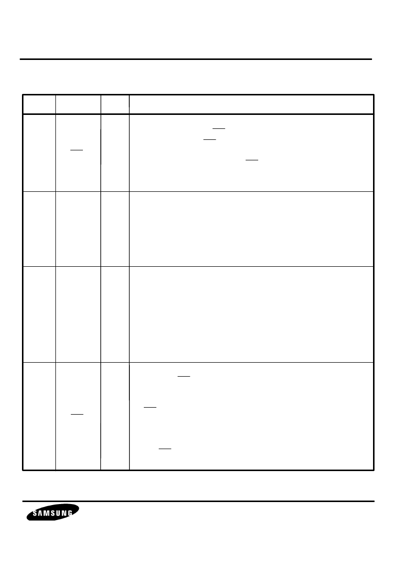
Pin No.
Symbol
Type
Description
Interrupt request
The modem can use IRQ to interrupt the host microprocessor
program execution. IRQ can be enabled in the modem interface
memory to be asserted in response to a specified change of
conditions in the modem status. IRQ is an open drain output
and must be connected to an external pull up resistor of suitable
value ( typically, a 5.6 K
, 1/4 watt, 5% resistor is adequate ).
63
19
27
7
IRQ
TXDI
RXDO
RTS
O
I
O
I
Receive data output
RXDO is the modem receive data output.
Received data is output to the DTE via the RXDO pin in both
serial and parallel data modes ( PDME bit set or reset ).
When receiving data, the modem outputs a data bit on the falling
edge of DCLK.
The center of RXDO bits coincides with the rising edge of DCLK,
thus, the DTE should read RXDO on the rising edge of DCLK.
Request to send
When the RTS input is forced low, the transmitter starts transmitting
the modem training sequence according to the selected configuration.
Once the training sequence has been transmitted ( signaled by the
CTS pin and CTSB bit becoming active ), data present at either the
TXDI input pin in serial mode ( PDME bit is reset ) or written into the
DBFR register in parallel mode ( PDME bit is set ) is modulated and
transmitted.
The RTS input pin is logically ORed with the RTSB bit in the
interface memory.
PIN DESCRIPTION
( Continued )
相關(guān)PDF資料 |
PDF描述 |
|---|---|
| KS16116-02 | 9600 bps FAX MODEM(9600bps傳真調(diào)制解調(diào)器) |
| KS16117-02 | 14400 bps FAX MODEM(14400bps傳真調(diào)制解調(diào)器) |
| KS16118 | 9600bps FAX super one-chip(9600bps傳真調(diào)制解調(diào)器) |
| KS16120B | DSP for Digital Answering Phone(用于數(shù)字應(yīng)答電話的DSP) |
| KS16121 | DSP for Digital Answering Phone(用于數(shù)字應(yīng)答電話的DSP) |
相關(guān)代理商/技術(shù)參數(shù) |
參數(shù)描述 |
|---|---|
| KS16114 | 制造商:SAMSUNG 制造商全稱:Samsung semiconductor 功能描述:9600/14400 bps FAX MODEM |
| KS16-14 | 制造商:MAJOR 功能描述: |
| KS-16287L1 | 制造商:WSTELC 功能描述: |
| KS-16287L2 | 制造商:WSTELC 功能描述: |
| KS16390 | 制造商: 功能描述: 制造商:Cornell Dubilier Electronics 功能描述: 制造商:undefined 功能描述: |
發(fā)布緊急采購,3分鐘左右您將得到回復(fù)。