- 您現(xiàn)在的位置:買賣IC網(wǎng) > PDF目錄377798 > LXT332 (Digital Data Communications GmbH) 3941 PDF資料下載
參數(shù)資料
| 型號: | LXT332 |
| 廠商: | Digital Data Communications GmbH |
| 英文描述: | 3941 |
| 中文描述: | 雙T1/E1線路接口單元與水晶無衰減 |
| 文件頁數(shù): | 5/32頁 |
| 文件大?。?/td> | 777K |
| 代理商: | LXT332 |
第1頁第2頁第3頁第4頁當(dāng)前第5頁第6頁第7頁第8頁第9頁第10頁第11頁第12頁第13頁第14頁第15頁第16頁第17頁第18頁第19頁第20頁第21頁第22頁第23頁第24頁第25頁第26頁第27頁第28頁第29頁第30頁第31頁第32頁
L1
eììì
/;7êê 'XDO 7ì(ì /LQH ,QWHUIDFH 8QLW ZLWK &U\VWDOeOHVV -LWWHU $WWHQXDWLRQ
éì
é
ê
é
TPOS0
(Bipolar)
TNEG0
(Bipolar)
RNEG0
(Bipolar)
DI
DI
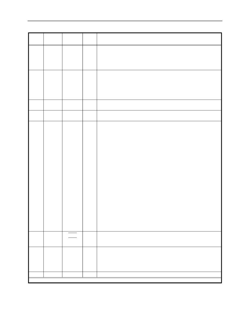
Transmit Positive and Negative Data - Port 0.
In the Bipolar I/O mode,
these pins are the positive and negative sides of a bipolar input pair for port
0. Data to be transmitted onto the twisted-pair line is input at these pins.
However, when the TRSTE pin is clocked by MCLK, the LXT332 switches
to a unipolar mode. Table 2 describes Unipolar mode pin functions.
Receive Positive and Negative Data - Port 0.
In the Bipolar I/O mode,
these pins are the data outputs from port 0. A signal on RNEG corresponds
to receipt of a negative pulse on RTIP/RRING. A signal on RPOS corre-
sponds to receipt of a positive pulse on RTIP/RRING. RNEG/RPOS outputs
are Non-Return-to-Zero (NRZ). In Host mode, CLKE determines the clock
edge at which these outputs are stable and valid.
Receive Clock - Port 0.
This clock is recovered from the input signal.
Under Loss of Signal (LOS) conditions, this output is derived from MCLK.
Serial Clock.
The Serial Clock shifts data into or out from the serial inter-
face register of the selected port.
Provides Violation insert, High Frequency Clock, or QRSS generation/detec-
tion functions for Port 0. Pin operation is determined by the VCQE pin.
éê
éé
è
RPOS0
(Bipolar)
DO
DO
ì
RCLK0
DO
SCLK
DI
ê
VCQ0
DI/O
Violation Insertion Function.
When the
V
iolation insertion function is
enabled, this pin is sampled on the falling edge of TCLK to control bipolar
violation (BPV) insertion. If High, a BPV is inserted at the next available
mark transmitted from port 0. A Low-to-High transition is required for each
subsequent violation insertion. (B8ZS and HDB3 zero suppression codes are
not violated.)
Clock Function.
When the
C
lock function is enabled, this pin outputs a
High Frequency Clock (12.352 MHz for T1, 16.384 MHz for E1) tied to the
jitter attenuated clock of port 0. If no JA clock is available, HFC is locked to
the 8x receive timing recovery clock.
Quasi Random Signal Source (QRSS) Function.
When the QRSS function
is enabled, a High on this pin enables the QRSS detection circuit and causes
the LXT332 to transmit the QRSS pattern onto the twisted-pair line from
port 0. For error-free QRSS transmission, TPOS0 must be held Low. To
insert errors into the pattern, TPOS must transition from Low to High (TPOS
is sampled on the falling edge of MCLK). A Low-to-High transition is
required for each subsequent violation insertion. (B8ZS and HDB3 zero
suppression codes are not violated.)
Interrupt Outputs.
The interrupt outputs go Low to flag the host processor
that the respective port has changed state. INT0 and INT1 are open drain
outputs. Each must be tied to VCC through a resistor.
Master Clock.
The master clock (1.544 MHz for T1, 2.048 MHz for E1)
input must be independent, free-running, continuously active and jitter free
for receiver operation. Since the transceivers derive their RCLK timing from
the MCLK input on Loss of Signal (LOS), MCLK cannot be derived from
RCLK.
Ground.
Ground return for power supply VCC.
é
è
ìí
ìì
INT1
INT0
DO
DO
ì
MCLK
DI
ìê
GND
–
7DEOH ì +RVW 0RGH 3LQ DQG %LSRODU +RVW 0RGH 3LQ 'HVFULSWLRQV
¤ FRQWLQXHG
3LQ
4)3
3LQ
3/&&
6\PERO
,2
ì
'HVFULSWLRQ
ì ', 'LJLWDO ,QSXWa '2 'LJLWDO 2XWSXWa ',2 'LJLWDO ,QSXW2XWSXWa $, $QDORJ ,QSXWa $2 $QDORJ 2XWSXW
相關(guān)PDF資料 |
PDF描述 |
|---|---|
| LXT334 | Quad Short Haul Transceiver with Clock Recovery |
| LXT335 | Quad Short Haul PCM Analog Interface |
| LXT350 | Integrated T1/E1 S/H Transceivers With Crystal-less Jitter Attenuation |
| LXT350QE | Integrated T1/E1 S/H Transceivers With Crystal-less Jitter Attenuation |
| LXT351 | T1/E1 Short Haul Transceiver with Crystal-less Jitter Attenuation |
相關(guān)代理商/技術(shù)參數(shù) |
參數(shù)描述 |
|---|---|
| LXT332PE | 制造商:未知廠家 制造商全稱:未知廠家 功能描述:Line Interface |
| LXT332QE | 制造商:未知廠家 制造商全稱:未知廠家 功能描述:Line Interface |
| LXT334 | 制造商:LVL1 制造商全稱:LVL1 功能描述:Quad Short Haul Transceiver with Clock Recovery |
| LXT334&LXT304A | 制造商:未知廠家 制造商全稱:未知廠家 功能描述:LXT334 & LXT304A - LXT334 & LXT304A ?Low Cost & High Performance Quad E1 Interface Solution |
| LXT335 | 制造商:LVL1 制造商全稱:LVL1 功能描述:Quad Short Haul PCM Analog Interface |
發(fā)布緊急采購,3分鐘左右您將得到回復(fù)。