- 您現(xiàn)在的位置:買賣IC網(wǎng) > PDF目錄45033 > M37512F8H-XXXHP 8-BIT, FLASH, 4 MHz, MICROCONTROLLER, PQFP48 PDF資料下載
參數(shù)資料
| 型號(hào): | M37512F8H-XXXHP |
| 元件分類: | 微控制器/微處理器 |
| 英文描述: | 8-BIT, FLASH, 4 MHz, MICROCONTROLLER, PQFP48 |
| 封裝: | 7 X 7 MM, 0.50 MM PITCH, PLASTIC, LQFP-48 |
| 文件頁(yè)數(shù): | 30/89頁(yè) |
| 文件大小: | 877K |
| 代理商: | M37512F8H-XXXHP |
第1頁(yè)第2頁(yè)第3頁(yè)第4頁(yè)第5頁(yè)第6頁(yè)第7頁(yè)第8頁(yè)第9頁(yè)第10頁(yè)第11頁(yè)第12頁(yè)第13頁(yè)第14頁(yè)第15頁(yè)第16頁(yè)第17頁(yè)第18頁(yè)第19頁(yè)第20頁(yè)第21頁(yè)第22頁(yè)第23頁(yè)第24頁(yè)第25頁(yè)第26頁(yè)第27頁(yè)第28頁(yè)第29頁(yè)當(dāng)前第30頁(yè)第31頁(yè)第32頁(yè)第33頁(yè)第34頁(yè)第35頁(yè)第36頁(yè)第37頁(yè)第38頁(yè)第39頁(yè)第40頁(yè)第41頁(yè)第42頁(yè)第43頁(yè)第44頁(yè)第45頁(yè)第46頁(yè)第47頁(yè)第48頁(yè)第49頁(yè)第50頁(yè)第51頁(yè)第52頁(yè)第53頁(yè)第54頁(yè)第55頁(yè)第56頁(yè)第57頁(yè)第58頁(yè)第59頁(yè)第60頁(yè)第61頁(yè)第62頁(yè)第63頁(yè)第64頁(yè)第65頁(yè)第66頁(yè)第67頁(yè)第68頁(yè)第69頁(yè)第70頁(yè)第71頁(yè)第72頁(yè)第73頁(yè)第74頁(yè)第75頁(yè)第76頁(yè)第77頁(yè)第78頁(yè)第79頁(yè)第80頁(yè)第81頁(yè)第82頁(yè)第83頁(yè)第84頁(yè)第85頁(yè)第86頁(yè)第87頁(yè)第88頁(yè)第89頁(yè)

Feb 18, 2005
page 34 of 85
REJ03B0122-0101
7512 Group
[I2C START/STOP Condition Control Register
(S2D)] 003016
The I2C START/STOP condition control register (address 003016)
controls START/STOP condition detection.
Bits 0 to 4: START/STOP condition set bits (SSC4–SSC0)
SCL release time, setup time, and hold time change the detection
condition by value of the main clock divide ratio selection bit and
the oscillation frequency f(XIN) because these time are measured
by the internal system clock. Accordingly, set the proper value to
the START/STOP condition set bits (SSC4 to SSC0) in considered
of the system clock frequency. Refer to Table 11.
Do not set “000002” or an odd number to the START/STOP condi-
tion set bit (SSC4 to SSC0).
Refer to Table 12, the recommended set value to START/STOP
condition set bits (SSC4–SSC0) for each oscillation frequency.
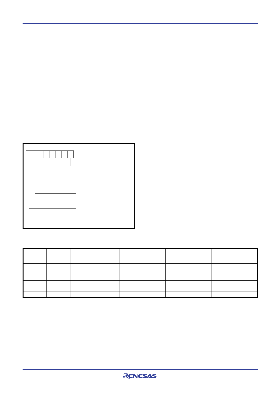
Fig. 37 Structure of I2C START/STOP condition control register
b7
b0
I2C START/STOP condition
control register
START/STOP condition set bits
SCL/SDA interrupt pin polarity
selection bit
0 : Falling edge active
1 : Rising edge active
SCL/SDA interrupt pin selection bit
0 : SDA valid
1 : SCL valid
STP/Low speed mode data receive
enable bit
0 : Disable
1 : Enable
SIS
SIP SSC4 SSC3 SSC2 SSC1 SSC0
(S2D : address 003016)
ARE
Bit 5: SCL/SDA interrupt pin polarity selection bit (SIP)
An interrupt can occur when detecting the falling or rising edge of
the SCL or SDA pin. This bit selects the polarity of the SCL or
SDA pin interrupt pin.
Bit 6: SCL/SDA interrupt pin selection bit (SIS)
This bit selects the pin of which interrupt becomes valid between
the SCL pin and the SDA pin.
Bit 7: STP/Low speed mode data receive enable bit
Selecting this bit “1” enables I2C to receive the start condition ad-
dress data even if the CPU is stopping or running at the low speed
mode. The detecting the falling edge of the SDA pin, built-in RC
oscillator begins oscillation, and receive the start condition ad-
dress data. After receiving the last bit of address data ( in case of
ACK clock bit =“1”, after receiving ACK bit), SCL/SDA interrupt
and I2C interrupt are requested at the same time. And then SCL
pin becomes low hold state as a result of becoming SCL pin low
hold bit “0”. During this state, it is possible to start the Xin oscilla-
tion. And after oscillation becomes stable, normal I2C operation
begins. If the start condition which is not satisfied the hold time of
start condition is input, SCL/SDA interrupt is requested.
In the low-speed mode, when this bit is set to "1", SCL/SDA inter-
rupt which occur by the rising or falling edge of SCL or SDA is
disabled.
Note: When changing the setting of the SCL/SDA interrupt pin polarity se-
lection bit, the SCL/SDA interrupt pin selection bit, or the I2C-BUS
interface enable bit ES0, the SCL/SDA interrupt request bit may be
set. When selecting the SCL/SDA interrupt source, disable the inter-
rupt before the SCL/SDA interrupt pin polarity selection bit, the SCL/
SDA interrupt pin selection bit, or the I2C-BUS interface enable bit
ES0 is set. Reset the request bit to “0” after setting these bits, and
enable the interrupt.
START/STOP
condition
control register
Oscillation
frequency
f(XIN) (MHz)
Note: Do not set “000002” or an odd number to the START/STOP condition set bits (SSC4 to SSC0).
Table 12 Recommended set value to START/STOP condition set bits (SSC4–SSC0) for each oscillation frequency
Main clock
divide ratio
System
clock
φ
(MHz)
SCL release time
(
s)
Setup time
(
s)
Hold time
(
s)
8
4
2
8
2
XXX11010
XXX11000
XXX00100
XXX01100
XXX01010
XXX00100
3.375
s (13.5 cycles)
3.125
s (12.5 cycles)
2.5
s (2.5 cycles)
3.25
s (6.5 cycles)
2.75
s (5.5 cycles)
2.5
s (2.5 cycles)
6.75
s (27 cycles)
6.25
s (25 cycles)
5.0
s (5 cycles)
6.5
s (13 cycles)
5.5
s (11 cycles)
5.0
s (5 cycles)
3.375
s (13.5 cycles)
3.125
s (12.5 cycles)
2.5
s (2.5 cycles)
3.25
s (6.5 cycles)
2.75
s (5.5 cycles)
2.5
s (2.5 cycles)
4
1
2
1
相關(guān)PDF資料 |
PDF描述 |
|---|---|
| M37512F8HP | 8-BIT, FLASH, 4 MHz, MICROCONTROLLER, PQFP48 |
| M37513EFFS | 8-BIT, UVPROM, 8 MHz, MICROCONTROLLER, CQCC100 |
| M37513M8-XXXGP | 8-BIT, MROM, 8 MHz, MICROCONTROLLER, PQFP100 |
| M37513EFFS | 8-BIT, UVPROM, 4 MHz, MICROCONTROLLER, CQCC100 |
| M37513M8-XXXGP | 8-BIT, MROM, 4 MHz, MICROCONTROLLER, PQFP100 |
相關(guān)代理商/技術(shù)參數(shù) |
參數(shù)描述 |
|---|---|
| M37512F8-XXXHP | 制造商:RENESAS 制造商全稱:Renesas Technology Corp 功能描述:SINGLE-CHIP 8-BIT CMOS MICROCOMPUTER |
| M37512FCHHP | 制造商:RENESAS 制造商全稱:Renesas Technology Corp 功能描述:SINGLE-CHIP 8-BIT CMOS MICROCOMPUTER |
| M37512FCHP | 制造商:RENESAS 制造商全稱:Renesas Technology Corp 功能描述:SINGLE-CHIP 8-BIT CMOS MICROCOMPUTER |
| M37512FCH-XXXHP | 制造商:RENESAS 制造商全稱:Renesas Technology Corp 功能描述:SINGLE-CHIP 8-BIT CMOS MICROCOMPUTER |
| M37512FC-XXXHP | 制造商:RENESAS 制造商全稱:Renesas Technology Corp 功能描述:SINGLE-CHIP 8-BIT CMOS MICROCOMPUTER |
發(fā)布緊急采購(gòu),3分鐘左右您將得到回復(fù)。