- 您現(xiàn)在的位置:買賣IC網(wǎng) > PDF目錄383540 > MAX9222EUM (MAXIM INTEGRATED PRODUCTS INC) Programmable DC-Balance 21-Bit Deserializers PDF資料下載
參數(shù)資料
| 型號(hào): | MAX9222EUM |
| 廠商: | MAXIM INTEGRATED PRODUCTS INC |
| 元件分類: | 通用總線功能 |
| 英文描述: | Programmable DC-Balance 21-Bit Deserializers |
| 中文描述: | QUAD LINE RECEIVER, PDSO48 |
| 封裝: | 6.10 MM, MO-153ED, TSSOP-48 |
| 文件頁(yè)數(shù): | 12/18頁(yè) |
| 文件大?。?/td> | 904K |
| 代理商: | MAX9222EUM |
第1頁(yè)第2頁(yè)第3頁(yè)第4頁(yè)第5頁(yè)第6頁(yè)第7頁(yè)第8頁(yè)第9頁(yè)第10頁(yè)第11頁(yè)當(dāng)前第12頁(yè)第13頁(yè)第14頁(yè)第15頁(yè)第16頁(yè)第17頁(yè)第18頁(yè)
M
Programmable DC-Balance
21-Bit Deserializers
12
______________________________________________________________________________________
Jitter due to droop is proportional to the droop and
transition time:
t
J
= t
T
x D (Eq 2)
where:
t
J
= jitter (s).
t
T
= transition time (s) (0 to 100%).
D = droop (% of signal amplitude).
Jitter due to 2% droop and assumed 1ns transition time is:
t
J
= 1ns x 0.02
t
J
= 20ps
The transition time in a real system depends on the fre-
quency response of the cable driven by the serializer.
The capacitor value decreases for a higher frequency
parallel clock and for higher levels of droop and jitter.
Use high-frequency, surface-mount ceramic capacitors.
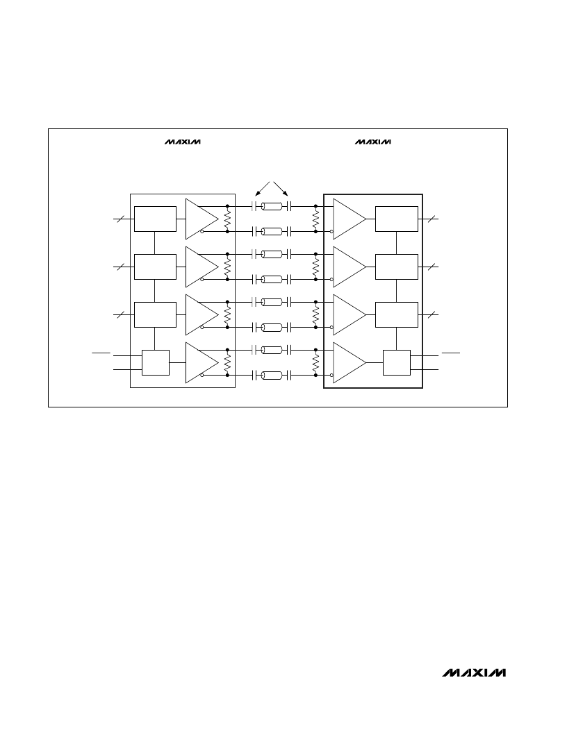
Equation 1 altered for four series capacitors (Figure 13) is:
C = - (4 x t
B
x DSV) / (ln (1 - D) x (R
T
+ R
O
)) (Eq 3)
Fail-Safe
The MAX9210/MAX9212/MAX9214/MAX9216/MAX9220/
MAX9222 have fail-safe LVDS inputs in non-DC-bal-
anced mode (Figure 1). Fail-safe drives the outputs low
when the corresponding LVDS input is open, undriven
and shorted, or undriven and parallel terminated. The
fail-safe on the LVDS clock input drives all outputs low.
Fail-safe does not operate in DC-balanced mode.
Input Bias and Frequency Detection
In DC-balanced mode, the inverting and noninverting
LVDS inputs are internally connected to +1.2V through
42k
(min) to provide biasing for AC-coupling (Figure 1).
A frequency-detection circuit on the clock input detects
when the input is not switching, or is switching at low
frequency. In this case, all outputs are driven low. To
prevent switching due to noise when the clock input is
not driven, bias the clock input to differential +15mV by
connecting a 10k
±1% pullup resistor between the
noninverting input and V
CC
, and a 10k
±1% pulldown
resistor between the inverting input and ground. These
(7 + 2):1
1:(9 - 2)
7
7
100
(7 + 2):1
1:(9 - 2)
7
7
100
(7 + 2):1
1:(9 - 2)
7
7
100
PLL
PLL
100
MAX9209
MAX9211
MAX9213
MAX9215
MAX9210
MAX9212
MAX9214
MAX9216
MAX9220
MAX9222
TxOUT
TxCLK OUT
RxIN
RxCLK IN
21:3 SERIALIZER
3:21 DESERIALIZER
PWRDWN
RxCLK OUT
RxOUT
PWRDWN
TxCLK IN
TxIN
HIGH-FREQUENCY CERAMIC
SURFACE-MOUNT CAPACITORS
Figure 13. Four Capacitors per Link, AC-Coupled, DC-Balanced Mode
相關(guān)PDF資料 |
PDF描述 |
|---|---|
| MAX9212ETM | Programmable DC-Balance 21-Bit Deserializers |
| MAX9214ETM | Programmable DC-Balance 21-Bit Deserializers |
| MAX9220ETM | Programmable DC-Balance 21-Bit Deserializers |
| MAX9222ETM | Programmable DC-Balance 21-Bit Deserializers |
| MAX9216ETM | Programmable DC-Balance 21-Bit Deserializers |
相關(guān)代理商/技術(shù)參數(shù) |
參數(shù)描述 |
|---|---|
| MAX9222EUM+ | 制造商:Maxim Integrated Products 功能描述:LVDS DESERLIZER 48TSSOP - Rail/Tube |
| MAX9222EUM+D | 制造商:Maxim Integrated Products 功能描述:LVDS DESERLIZER 48TSSOP - Rail/Tube |
| MAX9222EUM+T | 制造商:Maxim Integrated Products 功能描述:LVDS DESERLIZER 48TSSOP - Tape and Reel |
| MAX9222EUM+TD | 制造商:Maxim Integrated Products 功能描述:- Tape and Reel |
| MAX9222EUM-D | 制造商:Maxim Integrated Products 功能描述:PROGRAMMABLE DC-BALANCE 21-BIT DESERIALIZERS - Rail/Tube |
發(fā)布緊急采購(gòu),3分鐘左右您將得到回復(fù)。