- 您現(xiàn)在的位置:買賣IC網(wǎng) > PDF目錄377895 > MB86967PFV (FUJITSU LTD) LAN Controller with PC Card, ISA Bus, and General-purpose Bus Interfaces PDF資料下載
參數(shù)資料
| 型號: | MB86967PFV |
| 廠商: | FUJITSU LTD |
| 元件分類: | 微控制器/微處理器 |
| 英文描述: | LAN Controller with PC Card, ISA Bus, and General-purpose Bus Interfaces |
| 中文描述: | 1 CHANNEL(S), 10M bps, LOCAL AREA NETWORK CONTROLLER, PQFP80 |
| 封裝: | PLASTIC, LQFP-80 |
| 文件頁數(shù): | 55/129頁 |
| 文件大小: | 1499K |
| 代理商: | MB86967PFV |
第1頁第2頁第3頁第4頁第5頁第6頁第7頁第8頁第9頁第10頁第11頁第12頁第13頁第14頁第15頁第16頁第17頁第18頁第19頁第20頁第21頁第22頁第23頁第24頁第25頁第26頁第27頁第28頁第29頁第30頁第31頁第32頁第33頁第34頁第35頁第36頁第37頁第38頁第39頁第40頁第41頁第42頁第43頁第44頁第45頁第46頁第47頁第48頁第49頁第50頁第51頁第52頁第53頁第54頁當(dāng)前第55頁第56頁第57頁第58頁第59頁第60頁第61頁第62頁第63頁第64頁第65頁第66頁第67頁第68頁第69頁第70頁第71頁第72頁第73頁第74頁第75頁第76頁第77頁第78頁第79頁第80頁第81頁第82頁第83頁第84頁第85頁第86頁第87頁第88頁第89頁第90頁第91頁第92頁第93頁第94頁第95頁第96頁第97頁第98頁第99頁第100頁第101頁第102頁第103頁第104頁第105頁第106頁第107頁第108頁第109頁第110頁第111頁第112頁第113頁第114頁第115頁第116頁第117頁第118頁第119頁第120頁第121頁第122頁第123頁第124頁第125頁第126頁第127頁第128頁第129頁
55
MB86967
I
EXPLANATION OF ISA BUS MODE
1. Jumperless ISA Mode
In this mode, the LAN controller reads the I/O addresses and interrupt outputs from initialization data in external
E
2
PROM after the hardware reset at power-on, and initializes them. It takes about 50
μ
s until initialization is
completed.
This eliminates the need for on-board DIP switches for address decode selection. The initialization data can be
changed because the E
2
PROM can be read and written. Utilities for changing initialization data allow an
inexperienced user to retrieve contentions between I/O addresses and mount a LAN interface card in any
personal computer.
Only one byte is used for the initialization data in the E
2
PROM. Second and later bytes should be used to store
node ID. Data (node ID) at the second and later bytes should be read bit-by-bit, converted to parallel data, and
then written to the node ID registers (DLCR8 to DLCR15).
1.1 Setting at E
2
PROM
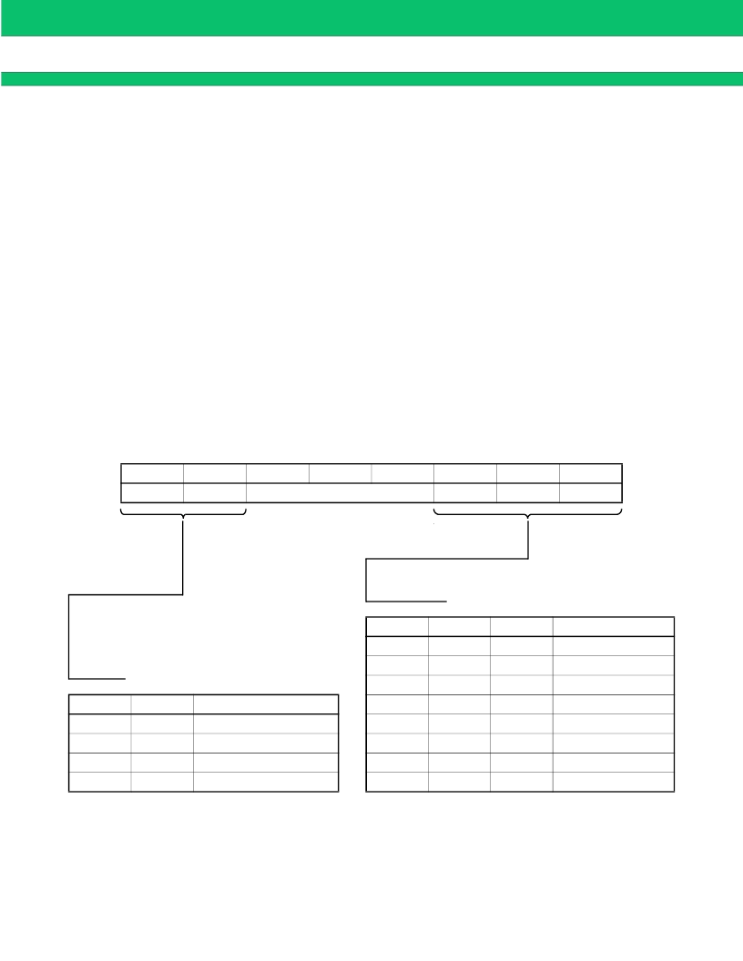
The initial values should be prewritten to the first byte in the E
2
PROM as shown in Figure 8; the node ID should
be prewritten to the second and later bytes.
After a hardware reset, the LAN controller reads the initialization data at the first one byte in E
2
PROM
automatically, and sets it at the BMPR19 internal register.
Bit 7
INTSEL1
Bit 6
INTSEL0
Bit 5
Bit 4
Not used
Bit 3
Bit 2
IOSEL2
Bit 1
IOSEL1
Bit 0
IOSEL0
IOMSEL2 IOMSEL1 IOMSEL0
0
0
0
0
0
1
0
1
1
0
1
0
1
1
1
1
I/O Base Address
260
H
to 27F
H
280
H
to 29F
H
2A0
H
to 2BF
H
240
H
to 25F
H
340
H
to 35F
H
320
H
to 33F
H
380
H
to 39F
H
300
H
to 31F
H
0
1
0
1
0
1
0
1
INTSEL1
0
0
1
1
INTSEL0
0
1
0
1
Interrupt Channel (Pin)
IRQ0
IRQ1
IRQ2
IRQ3
Setting I/O Addresses
Setting Interrupt Channels
Figure 8 Configuration of Bits at First One Byte in E
2
PROM
相關(guān)PDF資料 |
PDF描述 |
|---|---|
| MB86977 | IP PACKET FORWARDING ENGINE |
| MB86977PFV-G-BND | IP PACKET FORWARDING ENGINE |
| MB86H20 | SmartMPEG |
| MB86H21 | MPEG-2 Decoder with Integrated NDS ICAM |
| MB86H22 | MPEG-2 Decoder for ext. Temperature Range |
相關(guān)代理商/技術(shù)參數(shù) |
參數(shù)描述 |
|---|---|
| MB86977 | 制造商:FUJITSU 制造商全稱:Fujitsu Component Limited. 功能描述:IP PACKET FORWARDING ENGINE |
| MB86977PFV-G-BND | 制造商:FUJITSU 制造商全稱:Fujitsu Component Limited. 功能描述:IP PACKET FORWARDING ENGINE |
| MB86A21PMC-G-BNDE1 | 制造商:FUJITSU 功能描述: |
| MB86A21PMC-G-JNE1 | 制造商:FUJITSU 功能描述: |
| MB86A22PMC-ES-BNDE1 | 制造商:FUJITSU 功能描述: |
發(fā)布緊急采購,3分鐘左右您將得到回復(fù)。