- 您現(xiàn)在的位置:買賣IC網(wǎng) > PDF目錄69032 > MCV14ATI/SL 8-BIT, FLASH, 20 MHz, RISC MICROCONTROLLER, PDSO14 PDF資料下載
參數(shù)資料
| 型號: | MCV14ATI/SL |
| 元件分類: | 微控制器/微處理器 |
| 英文描述: | 8-BIT, FLASH, 20 MHz, RISC MICROCONTROLLER, PDSO14 |
| 封裝: | 3.90 MM, PLASTIC, SOIC-4 |
| 文件頁數(shù): | 39/84頁 |
| 文件大?。?/td> | 1007K |
| 代理商: | MCV14ATI/SL |
第1頁第2頁第3頁第4頁第5頁第6頁第7頁第8頁第9頁第10頁第11頁第12頁第13頁第14頁第15頁第16頁第17頁第18頁第19頁第20頁第21頁第22頁第23頁第24頁第25頁第26頁第27頁第28頁第29頁第30頁第31頁第32頁第33頁第34頁第35頁第36頁第37頁第38頁當前第39頁第40頁第41頁第42頁第43頁第44頁第45頁第46頁第47頁第48頁第49頁第50頁第51頁第52頁第53頁第54頁第55頁第56頁第57頁第58頁第59頁第60頁第61頁第62頁第63頁第64頁第65頁第66頁第67頁第68頁第69頁第70頁第71頁第72頁第73頁第74頁第75頁第76頁第77頁第78頁第79頁第80頁第81頁第82頁第83頁第84頁
MCV14A
DS41338B-page 42
Preliminary
2009 Microchip Technology Inc.
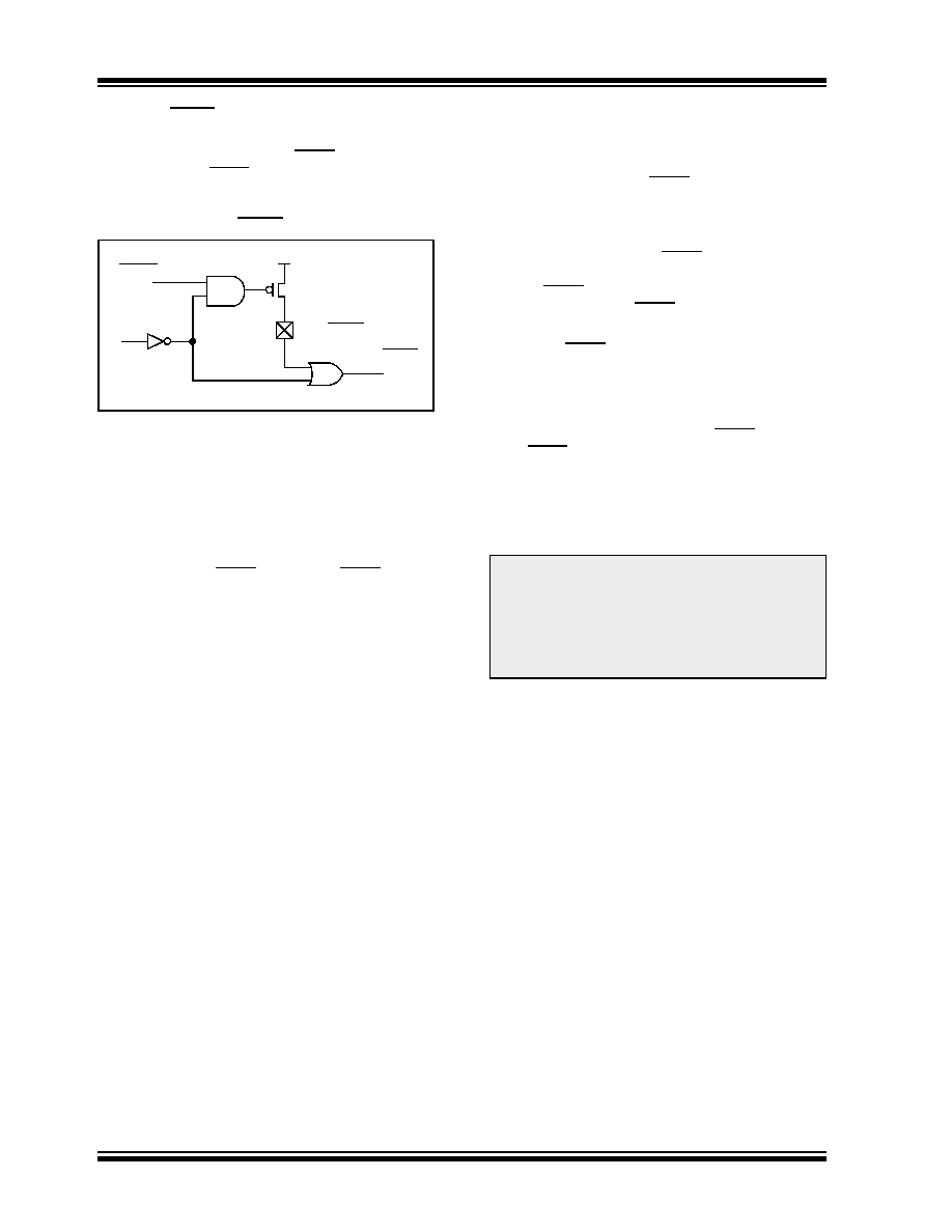
7.3.1
MCLR ENABLE
This Configuration bit, when unprogrammed (left in the
‘1’ state), enables the external MCLR function. When
programmed, the MCLR function is tied to the internal
FIGURE 7-6:
MCLR SELECT
7.4
Power-on Reset (POR)
The
MCV14A
device
incorporates
an
on-chip
Power-on Reset (POR) circuitry, which provides an
internal chip Reset for most power-up situations.
The on-chip POR circuit holds the chip in Reset until
VDD has reached a high enough level for proper
operation. To take advantage of the internal POR,
program the RB3/MCLR/VPP pin as MCLR and tie
through a resistor to VDD, or program the pin as RB3.
An internal weak pull-up resistor is implemented using
a transistor (refer to Table 11-5 for the pull-up resistor
ranges). This will eliminate external RC components
usually needed to create a Power-on Reset. A
maximum
rise time for
VDD is
specified.
See
Section 11.0 “Electrical Characteristics” for details.
When the device starts normal operation (exit the
Reset
condition),
device
operating
parameters
(voltage, frequency, temperature,...) must be met to
ensure operation. If these conditions are not met, the
device must be held in Reset until the operating
parameters are met.
A simplified block diagram of the on-chip Power-on
Reset circuit is shown in Figure 7-7.
The Power-on Reset circuit and the Device Reset
Timer (see Section 7.5 “Device Reset Timer (DRT)”)
circuit are closely related. On power-up, the Reset latch
is set and the DRT is reset. The DRT timer begins
counting once it detects MCLR to be high. After the
time-out period, which is typically 18 ms or 1 ms, it will
reset the Reset latch and thus end the on-chip Reset
signal.
A power-up example where MCLR is held low is shown
bringing MCLR high. The chip will actually come out of
Reset TDRT msec after MCLR goes high.
In Figure 7-9, the on-chip Power-on Reset feature is
being used (MCLR and VDD are tied together or the pin
is programmed to be RB3. The VDD is stable before the
start-up timer times out and there is no problem in get-
ting a proper Reset. However, Figure 7-10 depicts a
problem situation where VDD rises too slowly. The time
between when the DRT senses that MCLR is high and
when MCLR and VDD actually reach their full value, is
too long. In this situation, when the start-up timer times
out, VDD has not reached the VDD (min) value and the
chip may not function correctly. For such situations, we
recommend that external RC circuits be used to
achieve longer POR delay times (Figure 7-9).
For additional information, refer to Application Notes
AN522 “Power-Up Considerations” (DS00522) and
AN607 “Power-up Trouble Shooting” (DS00607).
RB3/MCLR/VPP
MCLRE
Internal MCLR
RBWU
Note:
When the device starts normal operation
(exit the Reset condition), device operat-
ing parameters (voltage, frequency, tem-
perature, etc.) must be met to ensure
operation. If these conditions are not met,
the device must be held in Reset until the
operating conditions are met.
相關PDF資料 |
PDF描述 |
|---|---|
| MCV14AI/P | 8-BIT, FLASH, 20 MHz, RISC MICROCONTROLLER, PDIP14 |
| MD8031AHB883B | 8-BIT, 12 MHz, MICROCONTROLLER, CDIP40 |
| MD8255A | 24 I/O, PIA-GENERAL PURPOSE, PDIP40 |
| MD82C52-/883 | 1 CHANNEL(S), 1M bps, SERIAL COMM CONTROLLER, CDIP28 |
| MR82C52-/883 | 1 CHANNEL(S), 1M bps, SERIAL COMM CONTROLLER, CQCC28 |
相關代理商/技術參數(shù) |
參數(shù)描述 |
|---|---|
| MCV15/10-GF-381 | 制造商:Phoenix Contact 功能描述:HEADER PCB VERTICAL 3.81MM 10WAY |
| MCV15/2-GF-381 | 制造商:Phoenix Contact 功能描述:HEADER PCB VERTICAL 3.81MM 2WAY |
| MCV15/3-GF-381 | 制造商:Phoenix Contact 功能描述:HEADER PCB VERTICAL 3.81MM 3WAY |
| MCV15/4-GF-381 | 制造商:Phoenix Contact 功能描述:HEADER PCB VERTICAL 3.81MM 4WAY |
| MCV15/5-GF-381 | 制造商:Phoenix Contact 功能描述:HEADER PCB VERTICAL 3.81MM 5WAY |
發(fā)布緊急采購,3分鐘左右您將得到回復。