- 您現(xiàn)在的位置:買賣IC網(wǎng) > PDF目錄371139 > MPX2102DP (Motorola, Inc.) Sensor PDF資料下載
參數(shù)資料
| 型號(hào): | MPX2102DP |
| 廠商: | Motorola, Inc. |
| 元件分類: | 壓力傳感器 |
| 英文描述: | Sensor |
| 中文描述: | 傳感器 |
| 文件頁數(shù): | 512/670頁 |
| 文件大小: | 6375K |
| 代理商: | MPX2102DP |
第1頁第2頁第3頁第4頁第5頁第6頁第7頁第8頁第9頁第10頁第11頁第12頁第13頁第14頁第15頁第16頁第17頁第18頁第19頁第20頁第21頁第22頁第23頁第24頁第25頁第26頁第27頁第28頁第29頁第30頁第31頁第32頁第33頁第34頁第35頁第36頁第37頁第38頁第39頁第40頁第41頁第42頁第43頁第44頁第45頁第46頁第47頁第48頁第49頁第50頁第51頁第52頁第53頁第54頁第55頁第56頁第57頁第58頁第59頁第60頁第61頁第62頁第63頁第64頁第65頁第66頁第67頁第68頁第69頁第70頁第71頁第72頁第73頁第74頁第75頁第76頁第77頁第78頁第79頁第80頁第81頁第82頁第83頁第84頁第85頁第86頁第87頁第88頁第89頁第90頁第91頁第92頁第93頁第94頁第95頁第96頁第97頁第98頁第99頁第100頁第101頁第102頁第103頁第104頁第105頁第106頁第107頁第108頁第109頁第110頁第111頁第112頁第113頁第114頁第115頁第116頁第117頁第118頁第119頁第120頁第121頁第122頁第123頁第124頁第125頁第126頁第127頁第128頁第129頁第130頁第131頁第132頁第133頁第134頁第135頁第136頁第137頁第138頁第139頁第140頁第141頁第142頁第143頁第144頁第145頁第146頁第147頁第148頁第149頁第150頁第151頁第152頁第153頁第154頁第155頁第156頁第157頁第158頁第159頁第160頁第161頁第162頁第163頁第164頁第165頁第166頁第167頁第168頁第169頁第170頁第171頁第172頁第173頁第174頁第175頁第176頁第177頁第178頁第179頁第180頁第181頁第182頁第183頁第184頁第185頁第186頁第187頁第188頁第189頁第190頁第191頁第192頁第193頁第194頁第195頁第196頁第197頁第198頁第199頁第200頁第201頁第202頁第203頁第204頁第205頁第206頁第207頁第208頁第209頁第210頁第211頁第212頁第213頁第214頁第215頁第216頁第217頁第218頁第219頁第220頁第221頁第222頁第223頁第224頁第225頁第226頁第227頁第228頁第229頁第230頁第231頁第232頁第233頁第234頁第235頁第236頁第237頁第238頁第239頁第240頁第241頁第242頁第243頁第244頁第245頁第246頁第247頁第248頁第249頁第250頁第251頁第252頁第253頁第254頁第255頁第256頁第257頁第258頁第259頁第260頁第261頁第262頁第263頁第264頁第265頁第266頁第267頁第268頁第269頁第270頁第271頁第272頁第273頁第274頁第275頁第276頁第277頁第278頁第279頁第280頁第281頁第282頁第283頁第284頁第285頁第286頁第287頁第288頁第289頁第290頁第291頁第292頁第293頁第294頁第295頁第296頁第297頁第298頁第299頁第300頁第301頁第302頁第303頁第304頁第305頁第306頁第307頁第308頁第309頁第310頁第311頁第312頁第313頁第314頁第315頁第316頁第317頁第318頁第319頁第320頁第321頁第322頁第323頁第324頁第325頁第326頁第327頁第328頁第329頁第330頁第331頁第332頁第333頁第334頁第335頁第336頁第337頁第338頁第339頁第340頁第341頁第342頁第343頁第344頁第345頁第346頁第347頁第348頁第349頁第350頁第351頁第352頁第353頁第354頁第355頁第356頁第357頁第358頁第359頁第360頁第361頁第362頁第363頁第364頁第365頁第366頁第367頁第368頁第369頁第370頁第371頁第372頁第373頁第374頁第375頁第376頁第377頁第378頁第379頁第380頁第381頁第382頁第383頁第384頁第385頁第386頁第387頁第388頁第389頁第390頁第391頁第392頁第393頁第394頁第395頁第396頁第397頁第398頁第399頁第400頁第401頁第402頁第403頁第404頁第405頁第406頁第407頁第408頁第409頁第410頁第411頁第412頁第413頁第414頁第415頁第416頁第417頁第418頁第419頁第420頁第421頁第422頁第423頁第424頁第425頁第426頁第427頁第428頁第429頁第430頁第431頁第432頁第433頁第434頁第435頁第436頁第437頁第438頁第439頁第440頁第441頁第442頁第443頁第444頁第445頁第446頁第447頁第448頁第449頁第450頁第451頁第452頁第453頁第454頁第455頁第456頁第457頁第458頁第459頁第460頁第461頁第462頁第463頁第464頁第465頁第466頁第467頁第468頁第469頁第470頁第471頁第472頁第473頁第474頁第475頁第476頁第477頁第478頁第479頁第480頁第481頁第482頁第483頁第484頁第485頁第486頁第487頁第488頁第489頁第490頁第491頁第492頁第493頁第494頁第495頁第496頁第497頁第498頁第499頁第500頁第501頁第502頁第503頁第504頁第505頁第506頁第507頁第508頁第509頁第510頁第511頁當(dāng)前第512頁第513頁第514頁第515頁第516頁第517頁第518頁第519頁第520頁第521頁第522頁第523頁第524頁第525頁第526頁第527頁第528頁第529頁第530頁第531頁第532頁第533頁第534頁第535頁第536頁第537頁第538頁第539頁第540頁第541頁第542頁第543頁第544頁第545頁第546頁第547頁第548頁第549頁第550頁第551頁第552頁第553頁第554頁第555頁第556頁第557頁第558頁第559頁第560頁第561頁第562頁第563頁第564頁第565頁第566頁第567頁第568頁第569頁第570頁第571頁第572頁第573頁第574頁第575頁第576頁第577頁第578頁第579頁第580頁第581頁第582頁第583頁第584頁第585頁第586頁第587頁第588頁第589頁第590頁第591頁第592頁第593頁第594頁第595頁第596頁第597頁第598頁第599頁第600頁第601頁第602頁第603頁第604頁第605頁第606頁第607頁第608頁第609頁第610頁第611頁第612頁第613頁第614頁第615頁第616頁第617頁第618頁第619頁第620頁第621頁第622頁第623頁第624頁第625頁第626頁第627頁第628頁第629頁第630頁第631頁第632頁第633頁第634頁第635頁第636頁第637頁第638頁第639頁第640頁第641頁第642頁第643頁第644頁第645頁第646頁第647頁第648頁第649頁第650頁第651頁第652頁第653頁第654頁第655頁第656頁第657頁第658頁第659頁第660頁第661頁第662頁第663頁第664頁第665頁第666頁第667頁第668頁第669頁第670頁

3–366
Motorola Sensor Device Data
For More Information On This Product,
Go to: www.freescale.com
should be avoided, both upstream and downstream. These locations include any obstruction or change such as valves, elbows,
flow splits, pumps, fans, etc. To increase the accuracy of pressure measurement in a dynamic system, allow at least 10 pipe /
duct diameters downstream of any change or obstruction and at least 2 pipe / duct diameters upstream. In addition the pipe / duct
diameter should be much larger than the diameter of the Pitot tube. The pipe / duct diameter should be at least 30 times the Pitot
tube diameter. Flow straighteners can also be used to minimize any variations in the direction of the flow. Also, when using a Pitot
tube, it is recommended that the static pressure tap be aligned in the same plane as the total pressure tap. On the Pitot–static tube,
the difference in location is assumed to be negligible.
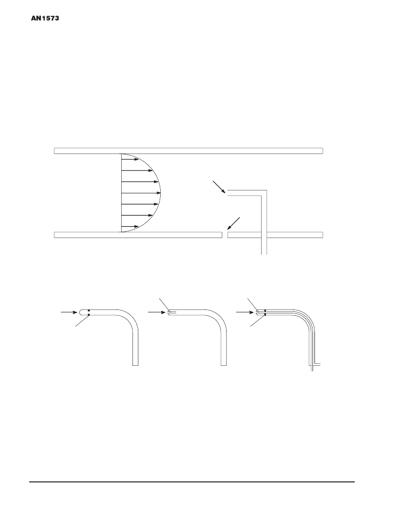
Flow–through pipes and ducts will result in a velocity field and dynamic pressure field that are non–uniform. At the wall of any
duct or pipe there exists a no–slip boundary due to friction. This means that at the wall itself the velocity of the fluid is zero. Figure
5 shows an imaginary velocity distribution in a duct. The shape of the distribution will depend on the fluid conditions, system flow
and pressure. In order to accurately determine the average dynamic pressure across a duct section, a series of total pressure
readings must be taken across the duct. These pressure measurements should be taken at different radii and clock positions
across the cross section of a round duct or at various width and height locations for a rectangular duct. Once this characterization
has been performed for the duct , a correlation can be easily made between the total pressure measurement at the center of the
duct relative to the average duct total pressure. This technique is also used to determine the velocity profile within the duct.
Velocity
Distribution
Static Pressure Tap
Pitot Tube
B
A
(A) Static Pressure
Probe
(B) Total Pressure
Pitot Tube
(C) Combination Static Pressure
and Total Pressure Pitot Tube
(Pitot–Static Tube)
Flow
Flow
Flow
B
B
A
A
Ps
Ps
Po
Po
Figure 5. Static and Total Pressure Measurements Within a Dynamic Fluid System.
Figure 6. Types of Pressure Probes
F
Freescale Semiconductor, Inc.
n
.
相關(guān)PDF資料 |
PDF描述 |
|---|---|
| MPX2102GP | Sensor |
| MPX2102GSX | Sensor |
| MPX2102GVP | Sensor |
| MPX2202A | Sensor |
| MPX2202AP | Sensor |
相關(guān)代理商/技術(shù)參數(shù) |
參數(shù)描述 |
|---|---|
| MPX2102GP | 功能描述:板上安裝壓力/力傳感器 UNIBODY COMPENSATED RoHS:否 制造商:Honeywell 工作壓力:0 bar to 4 bar 壓力類型:Gage 準(zhǔn)確性:+ / - 0.25 % 輸出類型:Digital 安裝風(fēng)格:Through Hole 工作電源電壓:5 V 封裝 / 箱體:SIP 端口類型:Dual Radial Barbed, Same sides |
| MPX2102GSX | 制造商:MOTOROLA 制造商全稱:Motorola, Inc 功能描述:Sensor |
| MPX2102GVP | 功能描述:板上安裝壓力/力傳感器 UNIBODY COMPENSATED RoHS:否 制造商:Honeywell 工作壓力:0 bar to 4 bar 壓力類型:Gage 準(zhǔn)確性:+ / - 0.25 % 輸出類型:Digital 安裝風(fēng)格:Through Hole 工作電源電壓:5 V 封裝 / 箱體:SIP 端口類型:Dual Radial Barbed, Same sides |
| MPX-2103 | 制造商:未知廠家 制造商全稱:未知廠家 功能描述:Ultra-Fast-Recovery Rectifier Diodes |
| MPX21W1100FA00MB00 | 功能描述:薄膜電容器 MP 3-X2 1000 pF 275 VAC 4x8.5x13.5 F PCM10 RoHS:否 制造商:Cornell Dubilier 產(chǎn)品類型: 電介質(zhì):Polyester 電容:0.047 uF 容差:10 % 電壓額定值:100 V 系列:225P 工作溫度范圍:- 55 C to + 85 C 端接類型:Radial 引線間隔:9.5 mm |
發(fā)布緊急采購,3分鐘左右您將得到回復(fù)。