- 您現(xiàn)在的位置:買(mǎi)賣(mài)IC網(wǎng) > PDF目錄69037 > MSC8101VT1500F (FREESCALE SEMICONDUCTOR INC) 64-BIT, 75 MHz, OTHER DSP, PBGA332 PDF資料下載
參數(shù)資料
| 型號(hào): | MSC8101VT1500F |
| 廠商: | FREESCALE SEMICONDUCTOR INC |
| 元件分類(lèi): | 數(shù)字信號(hào)處理 |
| 英文描述: | 64-BIT, 75 MHz, OTHER DSP, PBGA332 |
| 封裝: | 17 X 17 MM, LIDDED FLIP CHIP, PLASTIC, BGA-332 |
| 文件頁(yè)數(shù): | 51/104頁(yè) |
| 文件大小: | 1811K |
| 代理商: | MSC8101VT1500F |
第1頁(yè)第2頁(yè)第3頁(yè)第4頁(yè)第5頁(yè)第6頁(yè)第7頁(yè)第8頁(yè)第9頁(yè)第10頁(yè)第11頁(yè)第12頁(yè)第13頁(yè)第14頁(yè)第15頁(yè)第16頁(yè)第17頁(yè)第18頁(yè)第19頁(yè)第20頁(yè)第21頁(yè)第22頁(yè)第23頁(yè)第24頁(yè)第25頁(yè)第26頁(yè)第27頁(yè)第28頁(yè)第29頁(yè)第30頁(yè)第31頁(yè)第32頁(yè)第33頁(yè)第34頁(yè)第35頁(yè)第36頁(yè)第37頁(yè)第38頁(yè)第39頁(yè)第40頁(yè)第41頁(yè)第42頁(yè)第43頁(yè)第44頁(yè)第45頁(yè)第46頁(yè)第47頁(yè)第48頁(yè)第49頁(yè)第50頁(yè)當(dāng)前第51頁(yè)第52頁(yè)第53頁(yè)第54頁(yè)第55頁(yè)第56頁(yè)第57頁(yè)第58頁(yè)第59頁(yè)第60頁(yè)第61頁(yè)第62頁(yè)第63頁(yè)第64頁(yè)第65頁(yè)第66頁(yè)第67頁(yè)第68頁(yè)第69頁(yè)第70頁(yè)第71頁(yè)第72頁(yè)第73頁(yè)第74頁(yè)第75頁(yè)第76頁(yè)第77頁(yè)第78頁(yè)第79頁(yè)第80頁(yè)第81頁(yè)第82頁(yè)第83頁(yè)第84頁(yè)第85頁(yè)第86頁(yè)第87頁(yè)第88頁(yè)第89頁(yè)第90頁(yè)第91頁(yè)第92頁(yè)第93頁(yè)第94頁(yè)第95頁(yè)第96頁(yè)第97頁(yè)第98頁(yè)第99頁(yè)第100頁(yè)第101頁(yè)第102頁(yè)第103頁(yè)第104頁(yè)
MSC8101 Technical Data, Rev. 18
2-10
Freescale Semiconductor
Physical and Electrical Specifications
2.6.4.2 Power-On Reset Flow
Asserting the PORESET external pin initiates the power-on reset flow.
Note:
PORESET
and TRST must be asserted externally for the duration of the power-up sequence.
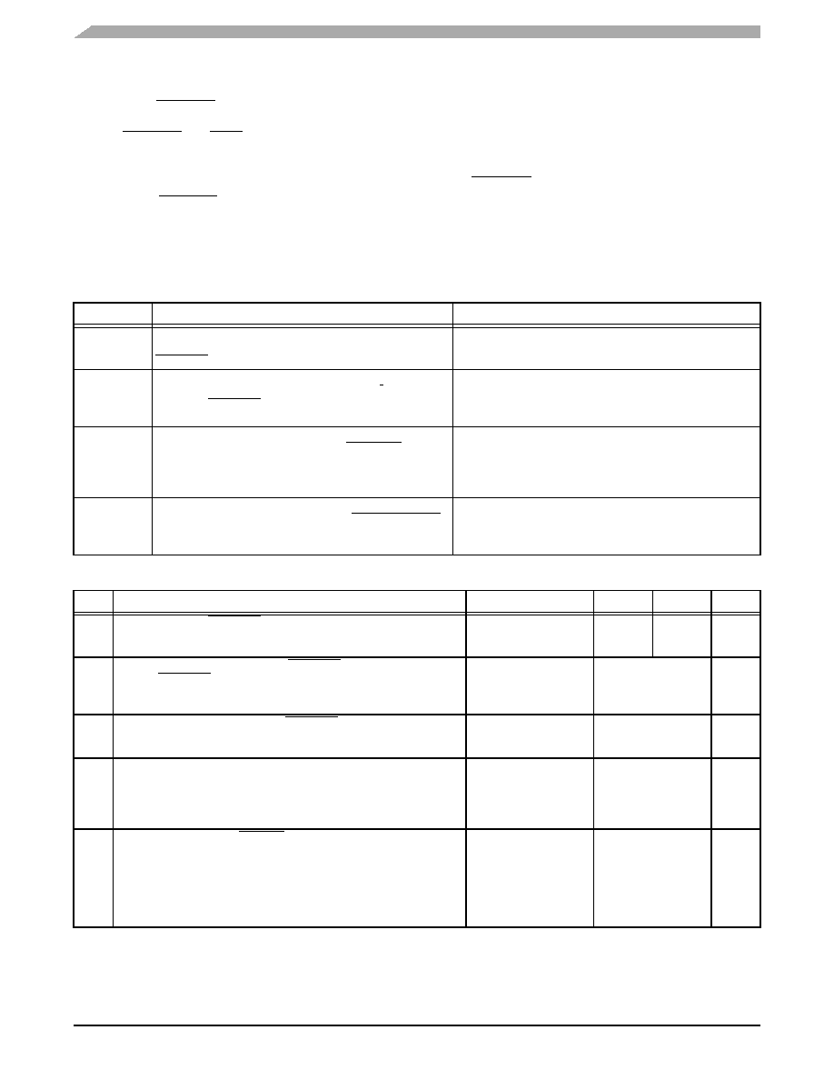
As Table 2-13 shows, the MSC8101 has five configuration pins, four of which are multiplexed with the SC140
EONCE Event (EE[0–1], EE[4–5]) pins and the fifth of which is the RSTCONF pin. These pins are sampled at the
rising edge of PORESET. In addition to these configuration pins, three (MODCK[1–3]) pins are sampled by the
MSC8101. The signals on these pins and the MODCK_H value in the Hard Reset Configuration Word determine
the PLL locking mode, by defining the ratio between the DSP clock, the bus clocks, and the CPM clock
frequencies.
Table 2-13.
External Configuration Signals
Pin
Description
Settings
RSTCONF
Reset Configuration
Input line sampled by the MSC8101 at the rising edge of
PORESET.
0
Reset Configuration Master.
1
Reset Configuration Slave.
DBREQ/ EE0
EONCE Event Bit 0
Input line sampled after SC140 core PLL locks. Holding EE0
high when PORESET is deasserted puts the SC140 into
Debug mode.
0
SC140 starts the normal processing
mode after reset.
1
SC140 enters Debug mode immediately
after reset.
HPE/EE1
Host Port Enable
Input line sampled at the rising edge of PORESET. If
asserted, the Host port is enabled, the system data bus is
32-bit wide, and the Host
must program the reset
configuration word.
0
Host port disabled (hardware reset
configuration enabled).
1
Host port enabled.
BTM[0–1]/
EE[4–5]
Boot Mode
Input lines sampled at the rising edge of PORESET, which
determine the MSC8101 Boot mode.
00
MSC8101 boots from external memory.
01
MSC8101 boots from HDI16.
10
Reserved.
11
Reserved.
Table 2-14.
Reset Timing
No.
Characteristics
Expression
Min
Max
Unit
1
Required external PORESET duration minimum
CLKIN = 18 MHz
CLKIN = 75 MHz
16
/ CLKIN
888.8
213.3
—
ns
2
Delay from deassertion of external PORESET to deassertion of
internal PORESET
CLKIN = 18 MHz
CLKIN = 75 MHz
1024
/ CLKIN
56.89
13.65
s
3
Delay from deassertion of internal PORESET to SPLL lock
SPLLMFCLK = 18 MHz
SPLLMFCLK = 25 MHz
800
/ SPLLMFCLK
44.4
32.0
s
4
Delay from SPLL lock to DLL lock
DLL enabled
— BCLK = 18 MHz
— BCLK = 75 MHz
DLL disabled
3073
/ BLCK
—
170.72
40.97
0.0
s
ns
5
Delay from SPLL lock to HRESET deassertion
DLL enabled
— BCLK = 18 MHz
— BCLK = 75 MHz
DLL disabled
— BCLK = 18 MHz
— BCLK = 75 MHz
3585
/ BLCK
512
/ BLCK
199.17
47.5
28.4
6.83
s
相關(guān)PDF資料 |
PDF描述 |
|---|---|
| MSC8101M1375F | 64-BIT, 68.75 MHz, OTHER DSP, PBGA332 |
| MSC8126VT8000 | 0-BIT, 500 MHz, OTHER DSP, PBGA431 |
| MSC8126TMP6400 | 0-BIT, 400 MHz, OTHER DSP, PBGA431 |
| MSM5055 | 4-BIT, MROM, 0.032768 MHz, MICROCONTROLLER, UUC94 |
| MSM6051L | 4-BIT, MROM, 0.032768 MHz, MICROCONTROLLER, UUC102 |
相關(guān)代理商/技術(shù)參數(shù) |
參數(shù)描述 |
|---|---|
| MSC8102 | 制造商:FREESCALE 制造商全稱(chēng):Freescale Semiconductor, Inc 功能描述:Quad Core 16-Bit Digital Signal Processor |
| MSC81020 | 制造商:STMICROELECTRONICS 制造商全稱(chēng):STMicroelectronics 功能描述:RF & MICROWAVE TRANSISTORS GENERAL PURPOSE AMPLIFIER APPLICATIONS |
| MSC8102M4000 | 制造商:FREESCALE 制造商全稱(chēng):Freescale Semiconductor, Inc 功能描述:Quad Core 16-Bit Digital Signal Processor |
| MSC8102M4400 | 制造商:FREESCALE 制造商全稱(chēng):Freescale Semiconductor, Inc 功能描述:Quad Core 16-Bit Digital Signal Processor |
| MSC8102RM | 制造商:FREESCALE 制造商全稱(chēng):Freescale Semiconductor, Inc 功能描述:Quad Core 16-Bit Digital Signal Processor |
發(fā)布緊急采購(gòu),3分鐘左右您將得到回復(fù)。