- 您現(xiàn)在的位置:買賣IC網(wǎng) > PDF目錄69040 > MT8952BS (ZARLINK SEMICONDUCTOR INC) 1 CHANNEL(S), 2.5M bps, SERIAL COMM CONTROLLER, PDSO28 PDF資料下載
參數(shù)資料
| 型號(hào): | MT8952BS |
| 廠商: | ZARLINK SEMICONDUCTOR INC |
| 元件分類: | 微控制器/微處理器 |
| 英文描述: | 1 CHANNEL(S), 2.5M bps, SERIAL COMM CONTROLLER, PDSO28 |
| 封裝: | 0.300 INCH, MS-013AE, SOIC-28 |
| 文件頁(yè)數(shù): | 12/32頁(yè) |
| 文件大?。?/td> | 602K |
| 代理商: | MT8952BS |
第1頁(yè)第2頁(yè)第3頁(yè)第4頁(yè)第5頁(yè)第6頁(yè)第7頁(yè)第8頁(yè)第9頁(yè)第10頁(yè)第11頁(yè)當(dāng)前第12頁(yè)第13頁(yè)第14頁(yè)第15頁(yè)第16頁(yè)第17頁(yè)第18頁(yè)第19頁(yè)第20頁(yè)第21頁(yè)第22頁(yè)第23頁(yè)第24頁(yè)第25頁(yè)第26頁(yè)第27頁(yè)第28頁(yè)第29頁(yè)第30頁(yè)第31頁(yè)第32頁(yè)

MT8952B
Data Sheet
2
Zarlink Semiconductor Inc.
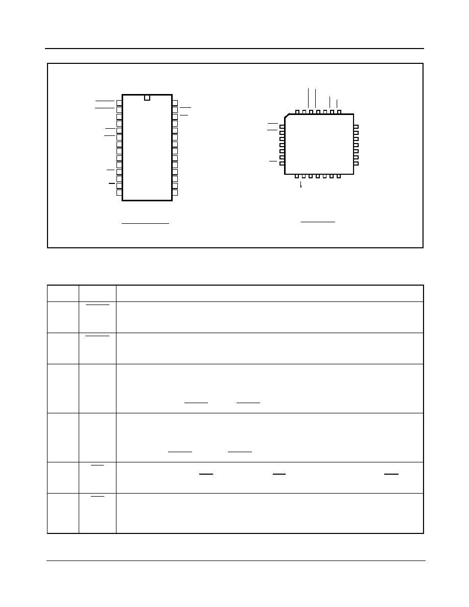
Figure 2 - Pin Connections
Pin Description
Pin No.
Name
Description
1TxCEN
Transmit Clock Enable - This active LOW input enables the transmit section in the External Timing
Mode. When LOW, CDSTo is enabled and when HIGH, CDSTo is in high impedance state. If the
Protocol Controller is in the Internal Timing Mode, this input is ignored.
2RxCEN Receive Clock Enable - This active LOW input enables the receive section in the External Timing
Mode. When LOW, CDSTi is enabled and when HIGH, the clock to the receive section is inhibited. If
the Protocol Controller is in the Internal Timing Mode, this input is ignored.
3CDSTo
C and D channel Output in ST-BUS format - This is the serial formatted data output from the
transmitter in NRZ form. It is in ST-BUS format if the Protocol Controller is in Internal Timing Mode
with the data in selected timeslots (0,2,3 and 4) and the C-channel information in timeslot No. 1. If
the Protocol Controller is in External Timing Mode, the formatted data is output on the rising edge of
the clock (CKi) when TxCEN LOW. If TxCEN is HIGH, CDSTo is in high impedance state.
4CDSTi
C and D channel Input in ST-BUS format - This is the serial formatted data input to the receiver in
NRZ form. It must be in ST-BUS format if the Protocol Controller is in Internal Timing Mode with
the input data in selected timeslots (0,2,3 and 4) and the C-channel information in timeslot No.1. If
the Controller is in External Timing Mode, the serial input data is sampled on the falling edge of the
clock CKi when RxCEN is LOW. If RxCEN is HIGH, the clock to receive section is inhibited.
5WD
Watch-Dog Timer output - Normally a HIGH level output, going LOW if the Watchdog timer times
out or if the external reset (RST) is held LOW. The WD output remains LOW as long as RST is held
LOW.
6IRQ
Interrupt Request Output (Open Drain) - This active LOW output notifies the controlling
microprocessor of an interrupt request. It goes LOW only when the bits in the Interrupt Enable
Register are programmed to acknowledge the source of the interrupt as defined in the Interrupt Flag
Register.
28 PIN PLCC
TxCEN
RxCEN
CDSTo
CDSTi
WD
IRQ
A0
A1
A2
A3
CS
E
R/W
VSS
VDD
RST
F0i
CKi
TEOP
REOP
D7
D6
D5
D4
D3
D2
D1
D0
28 PIN PDIP/SOIC
1
2
3
4
5
6
7
8
9
10
11
12
13
14
15
16
17
18
19
20
28
27
26
25
24
23
22
21
4
5
6
7
8
9
10
11
25
24
23
22
21
20
19
C
D
S
T
i
CKi
TEOP
REOP
D7
D6
D5
D4
WD
IRQ
A0
A1
A2
A3
CS
D
2
3
2
1
28
27
26
12 13
14
15
16
17
18
C
D
S
T
o
R
xC
E
N
T
xC
E
N
V
D
R
S
T
F
0i
E
R
/W
VS
S
D
0
D
1
D
3
相關(guān)PDF資料 |
PDF描述 |
|---|---|
| MT8952BPR | 1 CHANNEL(S), 2.5M bps, SERIAL COMM CONTROLLER, PQCC28 |
| MT8952BP1 | 1 CHANNEL(S), 2.5M bps, SERIAL COMM CONTROLLER, PQCC28 |
| MTA41110/P | SPECIALTY MICROPROCESSOR CIRCUIT, PDIP18 |
| MTA41110/SO | SPECIALTY MICROPROCESSOR CIRCUIT, PDSO18 |
| MTR80C186-12 | 16-BIT, 12.5 MHz, MICROPROCESSOR, CQCC68 |
相關(guān)代理商/技術(shù)參數(shù) |
參數(shù)描述 |
|---|---|
| MT8952BS1 | 制造商:Microsemi Corporation 功能描述:PB FREE HDLC PROTOCOL CONTROLLER - Rail/Tube 制造商:Zarlink Semiconductor Inc 功能描述:PB FREE HDLC PROTOCOL CONTROLLER |
| MT8960 | 制造商:ZARLINK 制造商全稱:Zarlink Semiconductor Inc 功能描述:Integrated PCM Filter Codec |
| MT8960AE | 制造商:ZARLINK 功能描述: |
| MT8960AE1 | 制造商:Microsemi Corporation 功能描述:AUD CODEC 1ADC / 1DAC 18PDIP - Rail/Tube |
| MT8961 | 制造商:MITEL 制造商全稱:Mitel Networks Corporation 功能描述:ISO2-CMOS Integrated PCM Filter Codec |
發(fā)布緊急采購(gòu),3分鐘左右您將得到回復(fù)。