- 您現(xiàn)在的位置:買賣IC網(wǎng) > PDF目錄370007 > PLS159 (NXP Semiconductors N.V.) Programmable logic sequencer 16 】 45 】 12 PDF資料下載
參數(shù)資料
| 型號(hào): | PLS159 |
| 廠商: | NXP Semiconductors N.V. |
| 英文描述: | Programmable logic sequencer 16 】 45 】 12 |
| 中文描述: | 可編程序邏輯16】45】12 |
| 文件頁(yè)數(shù): | 7/12頁(yè) |
| 文件大小: | 132K |
| 代理商: | PLS159 |

t
IH1
V
(OUTPUTS)
1.5V
1.5V
1.5V
1.5V
1.5V
1.5V
V
T
1.5V
1.5V
+3V
0V
+3V
0V
V
OH
V
OL
+3V
0V
I, B
(INPUTS)
CLK
F
(OUTPUTS)
OE
t
IH1
t
IS1
t
IS1
t
CKH
t
CKL
t
CKP
t
CKO
t
OD1
t
OE1
Flip-Flop Outputs
I, B
(INPUTS)
B
(OUTPUTS)
I, B
(OUTPUT
ENABLE)
t
PD
t
OE2
t
OD2
1.5V
+1.5V
+1.5V
V
T
+3V
0V
V
OH
V
OL
+3V
0V
Gate Outputs
Power-On Reset
+5V
0V
V
OH
V
OL
+3V
0V
4.5V
+3V
0V
t
t
CKO
1.5V
1.5V
1.5V
1.5V
1.5V
1.5V
1.5V
I, B
(INPUTS)
CLK
t
IS1
t
IS1
t
CKH
t
CKL
t
CKP
Philips Semiconductors Programmable Logic Devices
Product specification
PLS159A
Programmable logic sequencer
(16
×
45
×
12)
October 22, 1993
31
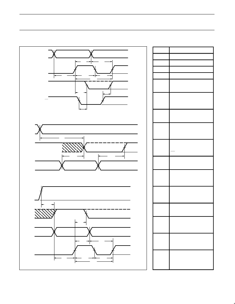
TIMING DIAGRAMS
TIMING DEFINITIONS
SYMBOL
PARAMETER
t
CKH
Width of input clock pulse.
t
CKL
Interval between clock pulses.
t
CKP
Clock period.
t
PRH
Width of preset input pulse.
t
IS1
Required delay between
beginning of valid input and
positive transition of clock.
t
IS2
Required delay between
beginning of valid input forced
at flip-flop output pins, and
positive transition of clock.
t
IH1
Required delay between
positive transition of clock and
end of valid input data.
t
IH2
Required delay between
positive transition of clock and
end of valid input data forced
at flip-flop output pins.
t
CKO
Delay between positive
transition of clock and when
outputs become valid (with
OE Low).
t
OE1
Delay between beginning of
Output Enable Low and when
outputs become valid.
t
OD1
Delay between beginning of
Output Enable High and
when outputs are in the
OFF-State.
t
PPR
Delay between V
(after
power-on) and when flip-flop
outputs become preset at “1”
(internal Q outputs at “0”).
t
PD
Propagation delay between
combinational inputs and
outputs.
t
OE2
Delay between predefined
Output Enable High, and
when combinational outputs
become valid.
t
OD2
Delay between predefined
Output Enable Low and when
combinational outputs are in
the OFF-State.
t
PRO
Delay between positive
transition of predefined
Preset/Reset input, and
when flip-flop outputs become
valid.
相關(guān)PDF資料 |
PDF描述 |
|---|---|
| PLS159AA | Programmable logic sequencer 16 】 45 】 12 |
| PLS159AN | Programmable logic sequencer 16 】 45 】 12 |
| PLS173A | Programmable logic array 22 】 42 】 10 |
| PLS173N | Programmable logic array 22 】 42 】 10 |
| PLS179A | Fuse-Programmable PLD |
相關(guān)代理商/技術(shù)參數(shù) |
參數(shù)描述 |
|---|---|
| PLS159/A | 制造商:未知廠家 制造商全稱:未知廠家 功能描述:PLD Sequencer (16 X 45 X 12) 18 MHz |
| PLS159A | 制造商:PHILIPS 制造商全稱:NXP Semiconductors 功能描述:Programmable logic sequencer 16 】 45 】 12 |
| PLS159AA | 制造商:PHILIPS 制造商全稱:NXP Semiconductors 功能描述:Programmable logic sequencer 16 】 45 】 12 |
| PLS159AF | 制造商:NXP Semiconductors 功能描述: |
| PLS159AN | 制造商:PHILIPS 制造商全稱:NXP Semiconductors 功能描述:Programmable logic sequencer 16 】 45 】 12 |
發(fā)布緊急采購(gòu),3分鐘左右您將得到回復(fù)。