- 您現(xiàn)在的位置:買賣IC網(wǎng) > PDF目錄378055 > PM5945-UTP5 (PMC-Sierra, Inc.) ATM PHYSICAL INTERFACE APPLICATION BOARD FOR CAT-5 UTP PDF資料下載
參數(shù)資料
| 型號(hào): | PM5945-UTP5 |
| 廠商: | PMC-Sierra, Inc. |
| 英文描述: | ATM PHYSICAL INTERFACE APPLICATION BOARD FOR CAT-5 UTP |
| 中文描述: | ATM物理接口貓應(yīng)用板- 5雙絞線 |
| 文件頁數(shù): | 66/84頁 |
| 文件大小: | 1666K |
| 代理商: | PM5945-UTP5 |
第1頁第2頁第3頁第4頁第5頁第6頁第7頁第8頁第9頁第10頁第11頁第12頁第13頁第14頁第15頁第16頁第17頁第18頁第19頁第20頁第21頁第22頁第23頁第24頁第25頁第26頁第27頁第28頁第29頁第30頁第31頁第32頁第33頁第34頁第35頁第36頁第37頁第38頁第39頁第40頁第41頁第42頁第43頁第44頁第45頁第46頁第47頁第48頁第49頁第50頁第51頁第52頁第53頁第54頁第55頁第56頁第57頁第58頁第59頁第60頁第61頁第62頁第63頁第64頁第65頁當(dāng)前第66頁第67頁第68頁第69頁第70頁第71頁第72頁第73頁第74頁第75頁第76頁第77頁第78頁第79頁第80頁第81頁第82頁第83頁第84頁
S
TANDARD
P
RODUCT
PMC-Sierra, Inc.
PM5945 -UTP5
PMC-940202 ISSUE 2. APRIL 7, 1995
______________________________________________________________________________________________
APP_SAPI_UTP5
______________________________________________________________________________________________
57
1
1
6
1
Vcc
0.1 uF
0
0.1 uF
0.1 uF
0.01 uF
0.01 uF
= Via connected
to Vcc
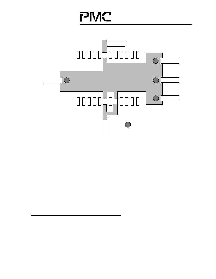
Power Plane and Decoupling of CY7B951
Pin 6 of the CY7B951 provides current for all output pins and is internally connected
to pin 17 and 19. Its voltage fluctuates as the outputs switch. When the voltage
difference between pin 6 and pins 17 and 19 will be amplified, causing the voltage
fluctuation on pin 6 to increase. When the voltage at pin 6 fluctuates, the outputs it
drives will start to draw more current which causes the voltage on pin 6 to fluctuate
further. Testing has shown this fluctuation can reach 2 V p-p.
The low impedance power plane puts pin 6, 17, and 19 at the same voltage level so
that if pin 6 fluctuates due to outputs switching, pin 17 and 19 will follow, preventing
any voltage difference between them.
Mounting Hole Clearance Requirements
The following clearances are required in order for the board to be mounted onto the
Vicksburg Motherboard:
On the component side, each mounting hole should have 0.25"x0.25" square
clearance centered at the center of the mounting hole.
相關(guān)PDF資料 |
PDF描述 |
|---|---|
| PM5945 | CONN |
| PM6341 | E1 TRANSCEIVER |
| PM6341-QI | Ultraframer DS3/E3/DS2/E2/DS1/E1/DS0 |
| PM6341-RI | Ultraframer DS3/E3/DS2/E2/DS1/E1/DS0 |
| PM6344-RI | KPSE SERIES |
相關(guān)代理商/技術(shù)參數(shù) |
參數(shù)描述 |
|---|---|
| PM594D | 制造商:未知廠家 制造商全稱:未知廠家 功能描述:Analog IC |
| PM594DS | 制造商:未知廠家 制造商全稱:未知廠家 功能描述:Analog IC |
| PM594K | 制造商:未知廠家 制造商全稱:未知廠家 功能描述:Analog IC |
| PM594KS | 制造商:未知廠家 制造商全稱:未知廠家 功能描述:Analog IC |
| PM594S | 制造商:未知廠家 制造商全稱:未知廠家 功能描述:Analog IC |
發(fā)布緊急采購,3分鐘左右您將得到回復(fù)。