- 您現(xiàn)在的位置:買賣IC網(wǎng) > PDF目錄378193 > RS5C372B (RICOH COMPANY LTD) I2C-bus Serial Interface Real Time Clock (8pin SSOP) PDF資料下載
參數(shù)資料
| 型號(hào): | RS5C372B |
| 廠商: | RICOH COMPANY LTD |
| 元件分類: | XO, clock |
| 英文描述: | I2C-bus Serial Interface Real Time Clock (8pin SSOP) |
| 中文描述: | REAL TIME CLOCK, PDSO8 |
| 封裝: | SSOP-8 |
| 文件頁(yè)數(shù): | 29/39頁(yè) |
| 文件大?。?/td> | 474K |
| 代理商: | RS5C372B |
第1頁(yè)第2頁(yè)第3頁(yè)第4頁(yè)第5頁(yè)第6頁(yè)第7頁(yè)第8頁(yè)第9頁(yè)第10頁(yè)第11頁(yè)第12頁(yè)第13頁(yè)第14頁(yè)第15頁(yè)第16頁(yè)第17頁(yè)第18頁(yè)第19頁(yè)第20頁(yè)第21頁(yè)第22頁(yè)第23頁(yè)第24頁(yè)第25頁(yè)第26頁(yè)第27頁(yè)第28頁(yè)當(dāng)前第29頁(yè)第30頁(yè)第31頁(yè)第32頁(yè)第33頁(yè)第34頁(yè)第35頁(yè)第36頁(yè)第37頁(yè)第38頁(yè)第39頁(yè)
RS5C372B
- 29 -
4.3. Periodic Interrupt
The /INTR pin outputs, the Periodic interrupt frequency select register, and the Interrupt output
select bit can be used to interrupt the CPU in a certain cycle. The Periodic interrupt frequency select register
can be used to select either one of two interrupt output modes: the pulse mode and the level mode.
Periodic interrupt frequency select register (D2-0 at internal address Eh)
CT2
CT1
CT0
Wave form
mode
0
0
0
-
OFF(H)
0
0
1
-
Fixed at “L”
0
1
0
Pulse mode
2Hz(Duty50%)
0
1
1
Pulse mode
1Hz(Duty50%)
1
0
0
Level mode
Every second (synchronized with second
count up)
1
0
1
Level mode
Every minute (00 second of every minute)
1
1
0
Level mode
Every hour ( 00 minute(s) 00 second(s) of
every hour )
1
1
1
Level mode
Every month (the 1st day 00 AM 00
minute(s) 00 second(s) of every month )
1) Pulse mode: Outputs 2Hz, 1Hz clock pulses. For relationships with counting up of seconds, see
the diagram on the next page.
*) When 32000Hz crystal is used
In the 2Hz clock pulse mode, 0.496s clock pulses and 0.504s clock pulse are
output alternately.
Duty cycle for 1Hz clock pulses becomes 50.4%
(“L” duration is 0.496s while “H” duration is 0.504s)
1) Level mode: One second, one minute or one month may be selected for an interrupt frequency.
Counting up of seconds is matched with falling edge of interrupt output.
2) When the clock error correction circuit is used, periodic interrupt frequency changes every 20
seconds.
Pulse mode: “L” duration of output pulses may change in the maximum range of ±3.784ms
(±3.875ms when 32.000kHz crystal is used.) For example, Duty will be 50±0.3784% (or
50±0.3875% when 32.000kHz crystal is used) at 1Hz.
Level mode: Frequency in one second may change in the maximum range of ±3.784ms
(±3.875ms when 32.000kHz crystal is used.)
Description
Frequency and falling timing
(Default)
Pulse mode
/INTR pin
(Counting up of seconds)
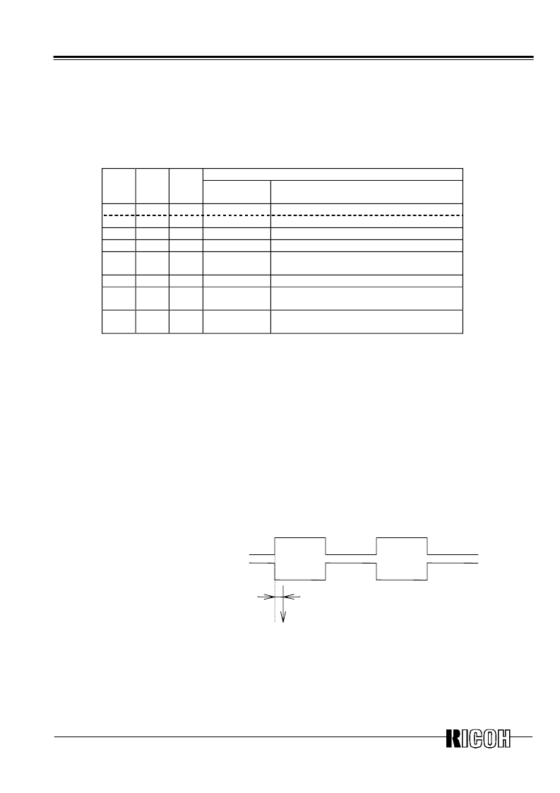
Approx. 92us (32.768KHz crystal is used)
Approx. 94us (32.000KHz crystal is used)
CTFG bit
*) Since counting up of seconds and the falling edge has a time lag of approx.
92μs (at 32.768kHz) (approx. 94μs when 32.000kHz crystal is used), time with
apparently approx. one second of delay from time of the real-time clock may be
read when time is read in synchronization with the falling edge of output.
相關(guān)PDF資料 |
PDF描述 |
|---|---|
| RS5C372B-E1 | I2C-bus Serial Interface Real Time Clock (8pin SSOP) |
| RS5C372B-E2 | I2C-bus Serial Interface Real Time Clock (8pin SSOP) |
| RS5C62 | REAL-TIME CLOCK |
| RSBL-9-S | Using Permanent Magnet, High sensitivity Two Poles Signal Relay RSB RELAYS |
| RSB-12 | Using Permanent Magnet, High sensitivity Two Poles Signal Relay RSB RELAYS |
相關(guān)代理商/技術(shù)參數(shù) |
參數(shù)描述 |
|---|---|
| RS5C372B-E1 | 制造商:RICOH 制造商全稱:RICOH electronics devices division 功能描述:I2C-bus Serial Interface Real Time Clock (8pin SSOP) |
| RS5C372B-E2 | 制造商:RICOH 制造商全稱:RICOH electronics devices division 功能描述:I2C-bus Serial Interface Real Time Clock (8pin SSOP) |
| RS5C373A | 制造商:未知廠家 制造商全稱:未知廠家 功能描述:Real-Time Clock |
| RS5C4FC | 制造商:Dialight 功能描述: |
| RS5C4F-C | 制造商:DIALIGHT 制造商全稱:Dialight Corporation 功能描述:StreetSense? RS Series LED Roadway Sign Light |
發(fā)布緊急采購(gòu),3分鐘左右您將得到回復(fù)。