- 您現(xiàn)在的位置:買賣IC網(wǎng) > PDF目錄383953 > TLC32040MFK (Texas Instruments, Inc.) ANALOG INTERFACE CIRCUIT PDF資料下載
參數(shù)資料
| 型號: | TLC32040MFK |
| 廠商: | Texas Instruments, Inc. |
| 英文描述: | ANALOG INTERFACE CIRCUIT |
| 中文描述: | 模擬接口電路 |
| 文件頁數(shù): | 5/30頁 |
| 文件大小: | 202K |
| 代理商: | TLC32040MFK |
第1頁第2頁第3頁第4頁當(dāng)前第5頁第6頁第7頁第8頁第9頁第10頁第11頁第12頁第13頁第14頁第15頁第16頁第17頁第18頁第19頁第20頁第21頁第22頁第23頁第24頁第25頁第26頁第27頁第28頁第29頁第30頁
TLC32040M
ANALOG INTERFACE CIRCUIT
POST OFFICE BOX 655303
DALLAS, TEXAS 75265
4–5
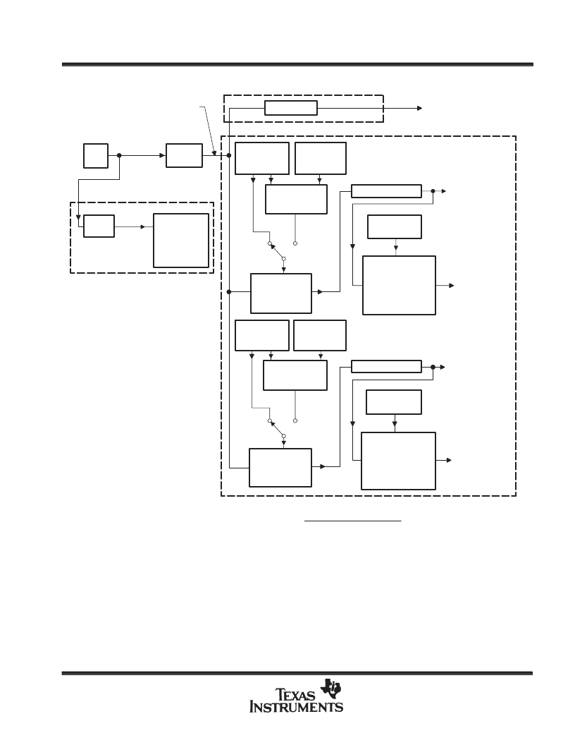
INTERNAL TIMING CONFIGURATION
Divide by 4
Shift Clock
1.296 MHz (1)
2.592 MHz (2)
Master Clock
5.184 MHZ (1)
10.368 MHZ (2)
20.736 MHz (1)
41.472 MHz (2)
XTAL
Osc
TMS320
DSP
Optional External Circuitry
for Full-Duplex Modems
153.6 kHz
Clock (1)
Divide
by 135
Commercial
External
Front-End
Full-Duplex
Split-Band
Filters
Divide by 2
TB Register
(6 Bits)
Low-Pass
Switched
Cap Filter
CLK = 288 kHz
Square Wave
D/A
Conversion
Frequency
Divide by 2
Band-Pass
Switched
Cap Filter
CLK = 288 kHz
Square Wave
RX Counter B
RB = 40, 7.2 kHz
RB = 36, 8.0 kHz
RB = 30, 9.6 kHz
RB = 20, 14.4 kHz
RB = 15, 19.2 kHz
TX Counter B
TB = 40, 7.2 kHz
TB = 36, 8.0 kHz
TB = 30, 9.6 kHz
TB = 20, 14.4 kHz
TB = 15, 19.2 kHz
576-kHz
Pulses
TX Counter A
[TA =
[TA =
(6 Bits)
9 (1)]
18 (2)]
TA’ Register
(6 Bits)
(2s Compl)
TA Register
(5 Bits)
Adder/
Subtractor
(6 Bits)
d0, d1 = 0,1
d0, d1 = 1,0
d0, d1 = 0,0
d0, d1 =
1,1
d0, d1 = 0,1
d0, d1 = 1,0
d0, d1 = 0,0
d0, d1 = 1, 1
SCF Clock Frequency =
Master Clock Frequency
2
×
Contents of Counter A
Adder/
Subtractor
(6 Bits)
RA’ Register
(6 Bits)
(2s Compl)
RA Register
(5 Bits)
RB Register
(6 Bits)
RX Counter A
[TA =
[TA =
(6 Bits)
9 (1)]
18 (2)]
576-kHz
Pulses
A/D
Conversion
Frequency
Split-band filtering can alternatively be performed after the analog input function via software in the SMJ320.
These control bits are described in the AIC DX data word format section.
NOTE: Frequency 1, 20.736 MHz is used to show how 153.6 kHz (for a commercially available modem split-band filter clock), popular speech
and modem sampling signal frequencies, and an internal 288-kHz switched-capacitor filter clock can be derived synchronously and as
submultiples of the crystal oscillator frequency. Since these derived frequencies are synchronous submultiples of the crystal frequency,
aliasing does not occur as the sampled analog signal passes between the analog converter and switched-capacitor filter stages.
Frequency 2, 41.472 MHz is used to show that the AIC can work with high-frequency signals, which are used by high-speed digital signal
processors
.
相關(guān)PDF資料 |
PDF描述 |
|---|---|
| TLC32040MJ | ANALOG INTERFACE CIRCUIT |
| TLC32044C | VOICE-BAND ANALOG INTERFACE CIRCUITS |
| TLC32045IN | VOICE-BAND ANALOG INTERFACE CIRCUITS |
| TLC32044E | VOICE-BAND ANALOG INTERFACE CIRCUITS |
| TLC32044I | VOICE-BAND ANALOG INTERFACE CIRCUITS |
相關(guān)代理商/技術(shù)參數(shù) |
參數(shù)描述 |
|---|---|
| TLC32040MJ | 制造商:TI 制造商全稱:Texas Instruments 功能描述:ANALOG INTERFACE CIRCUIT |
| TLC32041C | 制造商:TI 制造商全稱:Texas Instruments 功能描述:ANALOG INTERFACE CIRCUITS |
| TLC32041CFN | 制造商:TI 制造商全稱:Texas Instruments 功能描述:ANALOG INTERFACE CIRCUITS |
| TLC32041CN | 制造商:TI 功能描述:32041 |
| TLC32041I | 制造商:TI 制造商全稱:Texas Instruments 功能描述:ANALOG INTERFACE CIRCUITS |
發(fā)布緊急采購,3分鐘左右您將得到回復(fù)。