- 您現(xiàn)在的位置:買賣IC網(wǎng) > PDF目錄383953 > TLC32040MFK (Texas Instruments, Inc.) ANALOG INTERFACE CIRCUIT PDF資料下載
參數(shù)資料
| 型號(hào): | TLC32040MFK |
| 廠商: | Texas Instruments, Inc. |
| 英文描述: | ANALOG INTERFACE CIRCUIT |
| 中文描述: | 模擬接口電路 |
| 文件頁數(shù): | 7/30頁 |
| 文件大?。?/td> | 202K |
| 代理商: | TLC32040MFK |
第1頁第2頁第3頁第4頁第5頁第6頁當(dāng)前第7頁第8頁第9頁第10頁第11頁第12頁第13頁第14頁第15頁第16頁第17頁第18頁第19頁第20頁第21頁第22頁第23頁第24頁第25頁第26頁第27頁第28頁第29頁第30頁
TLC32040M
ANALOG INTERFACE CIRCUIT
POST OFFICE BOX 655303
DALLAS, TEXAS 75265
4–7
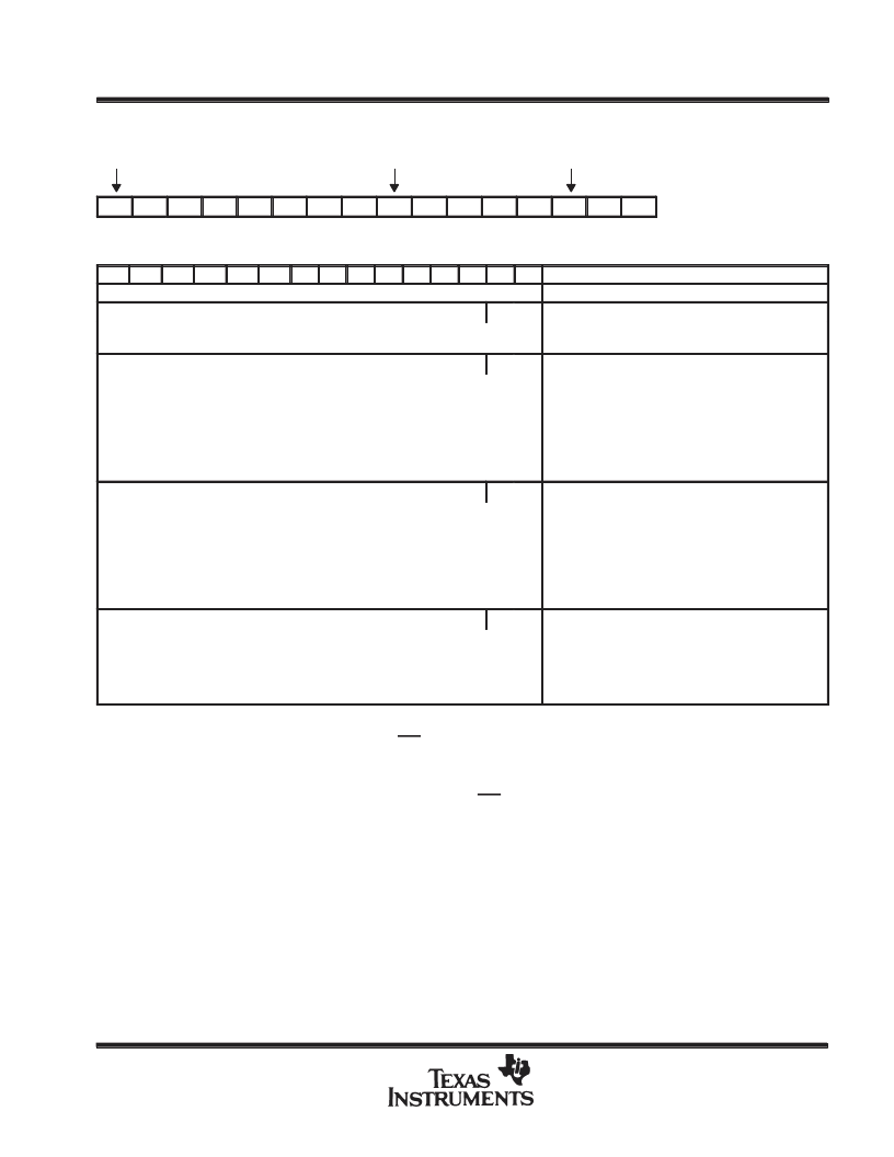
AIC DR or DX word bit pattern
A/D or D/A MSB,
1st bit sent
1st bit sent of 2nd byte
A/D or D/A LSB
D15
D14
D13
D12
D11
D10
D9
D8
D7
D6
D5
D4
D3
D2
D1
D0
AIC DX data word format section
d15
Primary DX serial communication protocol
d14
d13
d12
d11
d10
d9
d8
d7
d6
d5
d4
d2
d1
d0
COMMENTS
←
d15 (MSB) through d2 go to the D/A
→
converter register
0
0
The TX and RX Counter As are loaded with the TA and
RA register values. The TX and RX Counter Bs
areloaded with TB and RB register values.
The TX and Counter As are loaded with the TA + TA’
and RA + RA’ register values. The TX and RX Counter
Bs are loaded with the TB and RB register values.
NOTE: d1 = 0, d0 = 1 will cause the next D/A and A/D
conversion periods to be changed by the addition of TA’
and RA’ master clock cycles, in which TA’ and RA’ can
be positive or negative or zero. Please refer to Table 1.
AIC Responses to Improper Conditions.
The TX and Counter As are loaded with the TA - TA’
and RA - RA’ register values. The TX and RX Counter
Bs are loaded with the TB and RB register values.
NOTE: d1 = 0, d0 = 1 will cause the next D/A and A/D
conversion periods to be changed by the subtraction of
TA’ and RA’ Master Clock cycles, in which TA’ and RA
can be positive or negative or zero. Please refer to
Table 1. AIC Responses to Improper Conditions.
The TX and Counter As are loaded with the TA and
RA register values. The TX and RX Counter Bs are
loaded with the TB and RB register values. After a
delay of four shift-clock cycles, a secondary
transmission will immediately follow to program the
AIC to operate in the desired configuration.
←
d15 (MSB) through d2 go to the D/A
converter register
→
0
1
←
d15 (MSB) through d2 go to the D/A
→
converter register
1
0
←
d15 (MSB) through d2 go to the D/A
→
converter register
1
1
NOTE: Setting the two least significant bits to 1 in the normal transmission of DAC information (Primary Communications) to the AIC will initiate
Secondary Communications upon completion of the Primary Communications.
Upon completion of the Primary Communication, FSX will remain high for four shift-clock cycles and will then go low and initiate the
Secondary Communication. The timing specifications for the Primary and Secondary Communications are identical. in this manner, the
Secondary Communication, if initiated, is interleaved between successive Primary Communications. This interleaving prevents the
Secondary Communication from interfering with the Primary Communications and DAC timing, thus preventing the AIC from skipping a
DAC output. It is important to note that in the synchronous mode, FSR will not be asserted during Secondary Communications.
相關(guān)PDF資料 |
PDF描述 |
|---|---|
| TLC32040MJ | ANALOG INTERFACE CIRCUIT |
| TLC32044C | VOICE-BAND ANALOG INTERFACE CIRCUITS |
| TLC32045IN | VOICE-BAND ANALOG INTERFACE CIRCUITS |
| TLC32044E | VOICE-BAND ANALOG INTERFACE CIRCUITS |
| TLC32044I | VOICE-BAND ANALOG INTERFACE CIRCUITS |
相關(guān)代理商/技術(shù)參數(shù) |
參數(shù)描述 |
|---|---|
| TLC32040MJ | 制造商:TI 制造商全稱:Texas Instruments 功能描述:ANALOG INTERFACE CIRCUIT |
| TLC32041C | 制造商:TI 制造商全稱:Texas Instruments 功能描述:ANALOG INTERFACE CIRCUITS |
| TLC32041CFN | 制造商:TI 制造商全稱:Texas Instruments 功能描述:ANALOG INTERFACE CIRCUITS |
| TLC32041CN | 制造商:TI 功能描述:32041 |
| TLC32041I | 制造商:TI 制造商全稱:Texas Instruments 功能描述:ANALOG INTERFACE CIRCUITS |
發(fā)布緊急采購,3分鐘左右您將得到回復(fù)。