- 您現(xiàn)在的位置:買賣IC網(wǎng) > PDF目錄371187 > TMPR28051-3-SL5 Paired Cable; Number of Conductors:12; Conductor Size AWG:24; No. Strands x Strand Size:7 x 32; Jacket Material:Polyolefin; Number of Pairs:6; Impedance:100ohm; Voltage Nom.:300V RoHS Compliant: Yes PDF資料下載
參數(shù)資料
| 型號: | TMPR28051-3-SL5 |
| 英文描述: | Paired Cable; Number of Conductors:12; Conductor Size AWG:24; No. Strands x Strand Size:7 x 32; Jacket Material:Polyolefin; Number of Pairs:6; Impedance:100ohm; Voltage Nom.:300V RoHS Compliant: Yes |
| 中文描述: | TMPR28051 STS-1/AU-3(的STM - 0)映射為版本的設備5設備咨詢 |
| 文件頁數(shù): | 23/90頁 |
| 文件大小: | 1090K |
| 代理商: | TMPR28051-3-SL5 |
第1頁第2頁第3頁第4頁第5頁第6頁第7頁第8頁第9頁第10頁第11頁第12頁第13頁第14頁第15頁第16頁第17頁第18頁第19頁第20頁第21頁第22頁當前第23頁第24頁第25頁第26頁第27頁第28頁第29頁第30頁第31頁第32頁第33頁第34頁第35頁第36頁第37頁第38頁第39頁第40頁第41頁第42頁第43頁第44頁第45頁第46頁第47頁第48頁第49頁第50頁第51頁第52頁第53頁第54頁第55頁第56頁第57頁第58頁第59頁第60頁第61頁第62頁第63頁第64頁第65頁第66頁第67頁第68頁第69頁第70頁第71頁第72頁第73頁第74頁第75頁第76頁第77頁第78頁第79頁第80頁第81頁第82頁第83頁第84頁第85頁第86頁第87頁第88頁第89頁第90頁

Data Sheet
August 1999
TMPR28051 STS-1/AU-3 (STM-0) Mapper
9
Lucent Technologies Inc.
Pin Information
(continued)
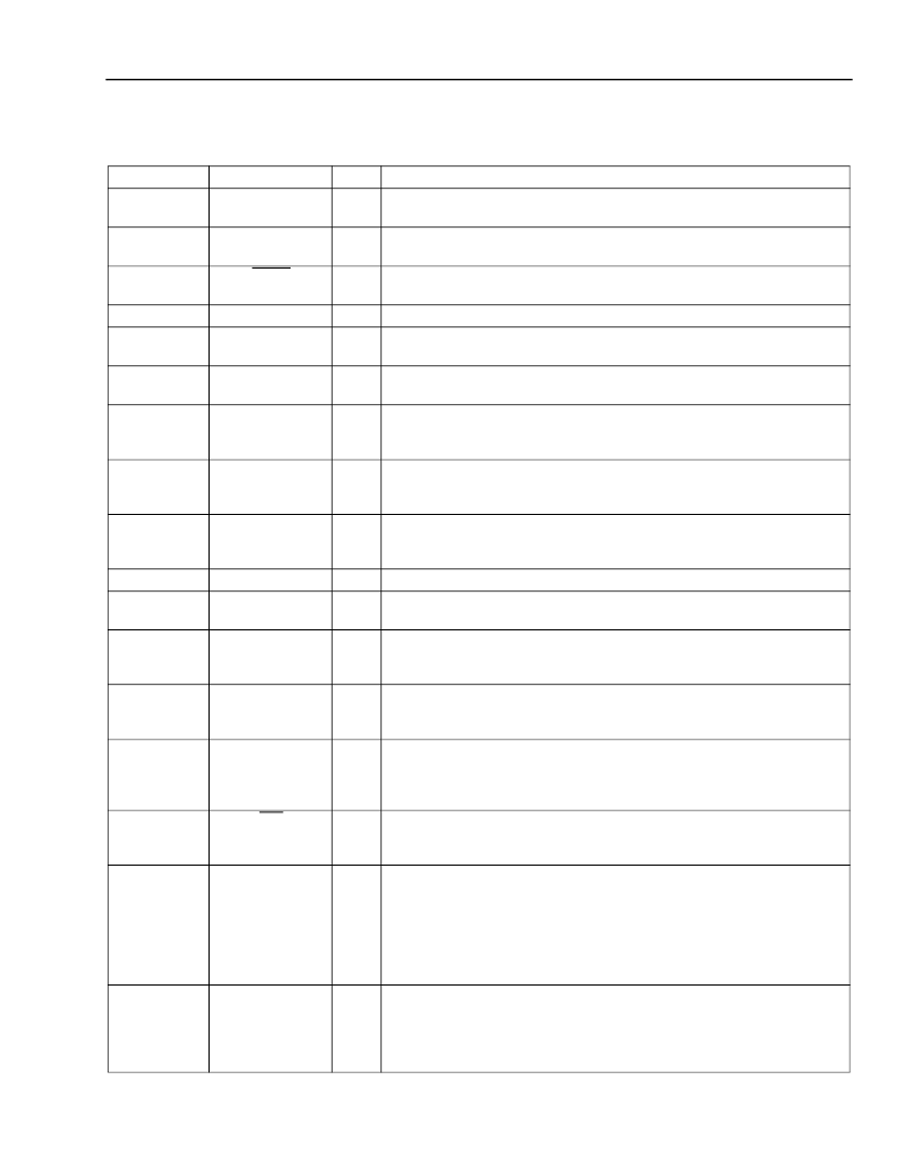
Table 1. Pin Descriptions
(continued)
* I
u
indicates an internal pull-up; I
d
indicates an internal pull-down. All I/O not explicitly stated with a buffer type are 5 V TTL compatible; they will
tolerate 5 V at their inputs.
Pin
185
Symbol
TDI
Type*
I
u
Name/Description
Boundary-Scan Input Data.
This pin has an internal 20 k
pull-up
resistor.
Boundary-Scan Mode Select.
This pin has an internal 20 k
pull-up
resistor.
Boundary-Scan Reset (Active-Low).
This pin has an internal 20 k
pull-down resistor.
Boundary-Scan Output Data.
Transmit STS-1 Clock.
The STS-1 clock can be 51.84 MHz for serial
input data, or 19.44 MHz or 6.48 MHz for byte-wide data.
Transmit STS-1 Sync.
The STS-1 sync pulse can be either J0 for
8 kHz only or a composite of J0J1V1 for 2 kHz.
Transmit STS-1 Data.
In the byte-wide output mode, this is bit 6—bit 0
of the data bus. TSTS1DATA7 is the most significant bit of the output
byte.
Transmit STS-1 Parity.
The parity output is only defined for byte-wide
data. The device can be provisioned to source either an odd or even
parity.
Transmit STS-1 Serial Data/Transmit STS-1 Data Bit 7 (MSB).
In
serial mode, this pin provides 51.84 Mbits/s serial data. In parallel
mode, this pin provides TSTS1DATA7.
Transmit STS-1 Output Clock.
Receive STS-1 Clock.
The STS-1 clock can be 51.84 MHz for serial
input data, or 19.44 MHz or 6.48 MHz for byte-wide data.
Receive STS-1 Data.
In the byte-wide input mode, this is the data bus
with RSTS1DATA7 as the most significant bit of the input byte. This pin
has an internal 100 k
pull-up resistor.
Receive STS-1 Parity.
The parity input is only defined for byte-wide
data. The device can be provisioned to accept either an odd or even
parity. This pin has an internal 100 k
pull-up resistor.
Receive STS-1 Serial Data.
If the device is operating in the serial
mode, then RSTS1SERIAL is used as the input data pin. In the bus
mode, this pin is used to synchronize byte 1 of 3 (see Figure 15,
page 71).
In-Circuit Test Control (Active-Low).
If ICT is forced low, all output
pins are placed in the high-impedance state. This pin has an internal
20 k
pull-up resistor.
Ground Reference for Digital Circuitry.
186
TMS
I
u
188
TRST
I
d
189
89
TDO
O
I
TSTS1CLKIN
90
TSTS1SYNC
I
92,
94—99
TSTS1DATA[6:0]
O
100
TSTS1PAR
O
91
TSTS1SERIAL/
TSTS1DATA7
O
88
82
TSTS1CLKOUT
RSTS1CLK
O
I
80, 78—75,
73—71
RSTS1DATA[7:0]
I
u
70
RSTS1PAR
I
u
85
RSTS1SERIAL
I
156
ICT
I
u
1, 2, 21, 31,
51, 53, 54, 74,
79, 81, 84,
103, 105, 125,
135, 155, 157,
158, 177, 182,
187, 207
12, 26, 40, 52,
65, 69, 83, 93,
104, 111, 116,
121, 130, 144,
150, 168, 196
V
SS
I
V
DD
I
Power Supply for Digital Circuitry.
相關PDF資料 |
PDF描述 |
|---|---|
| TMPR28051 | TMPR28051 STS-1/AU-3 (STM-0) Mapper Device Advisory for Version 5 of the Device |
| TMUX03155 | TMUX03155 STS-3/STM-1 (AU-4) Multiplexer/Demultiplexer |
| TMXF28155 | TMXF28155 Super Mapper 155/51 Mbits/s SONET/SDH x28/x21 DS1/E1 |
| TMXF84622 | TMXF84622 155 Mbits/s/622 Mbits/s Interface SONET/SDH x84/x63 Ultramapper |
| TN2-L-H-3V | SLIM POLARIZED RELAY |
相關代理商/技術參數(shù) |
參數(shù)描述 |
|---|---|
| TMPR28051-SL | 制造商:未知廠家 制造商全稱:未知廠家 功能描述:ATM/SONET MAPPER|QFP|208PIN|PLASTIC |
| TMPR3904F | 制造商:未知廠家 制造商全稱:未知廠家 功能描述:MICROPROCESSOR|32-BIT|CMOS|QFP|208PIN|PLASTIC |
| TMPR3907F | 制造商:未知廠家 制造商全稱:未知廠家 功能描述:MICROPROCESSOR|32-BIT|CMOS|QFP|208PIN|PLASTIC |
| TMPR3911 | 制造商:TOSHIBA 制造商全稱:Toshiba Semiconductor 功能描述:32-Bit TX System RISC TX39 Family |
| TMPR3912 | 制造商:TOSHIBA 制造商全稱:Toshiba Semiconductor 功能描述:32-Bit TX System RISC TX39 Family |
發(fā)布緊急采購,3分鐘左右您將得到回復。