- 您現(xiàn)在的位置:買賣IC網(wǎng) > PDF目錄382649 > TMX320F2810GHHMEP (Texas Instruments, Inc.) Digital Signal Processors PDF資料下載
參數(shù)資料
| 型號(hào): | TMX320F2810GHHMEP |
| 廠商: | Texas Instruments, Inc. |
| 元件分類: | 數(shù)字信號(hào)處理 |
| 英文描述: | Digital Signal Processors |
| 中文描述: | 數(shù)字信號(hào)處理器 |
| 文件頁(yè)數(shù): | 31/103頁(yè) |
| 文件大?。?/td> | 1341K |
| 代理商: | TMX320F2810GHHMEP |
第1頁(yè)第2頁(yè)第3頁(yè)第4頁(yè)第5頁(yè)第6頁(yè)第7頁(yè)第8頁(yè)第9頁(yè)第10頁(yè)第11頁(yè)第12頁(yè)第13頁(yè)第14頁(yè)第15頁(yè)第16頁(yè)第17頁(yè)第18頁(yè)第19頁(yè)第20頁(yè)第21頁(yè)第22頁(yè)第23頁(yè)第24頁(yè)第25頁(yè)第26頁(yè)第27頁(yè)第28頁(yè)第29頁(yè)第30頁(yè)當(dāng)前第31頁(yè)第32頁(yè)第33頁(yè)第34頁(yè)第35頁(yè)第36頁(yè)第37頁(yè)第38頁(yè)第39頁(yè)第40頁(yè)第41頁(yè)第42頁(yè)第43頁(yè)第44頁(yè)第45頁(yè)第46頁(yè)第47頁(yè)第48頁(yè)第49頁(yè)第50頁(yè)第51頁(yè)第52頁(yè)第53頁(yè)第54頁(yè)第55頁(yè)第56頁(yè)第57頁(yè)第58頁(yè)第59頁(yè)第60頁(yè)第61頁(yè)第62頁(yè)第63頁(yè)第64頁(yè)第65頁(yè)第66頁(yè)第67頁(yè)第68頁(yè)第69頁(yè)第70頁(yè)第71頁(yè)第72頁(yè)第73頁(yè)第74頁(yè)第75頁(yè)第76頁(yè)第77頁(yè)第78頁(yè)第79頁(yè)第80頁(yè)第81頁(yè)第82頁(yè)第83頁(yè)第84頁(yè)第85頁(yè)第86頁(yè)第87頁(yè)第88頁(yè)第89頁(yè)第90頁(yè)第91頁(yè)第92頁(yè)第93頁(yè)第94頁(yè)第95頁(yè)第96頁(yè)第97頁(yè)第98頁(yè)第99頁(yè)第100頁(yè)第101頁(yè)第102頁(yè)第103頁(yè)

TMS320F2810, TMS320F2812
DIGITAL SIGNAL PROCESSORS
SPRS174B
–
APRIL 2001
–
REVISED SEPTEMBER 2001
31
POST OFFICE BOX 1443
HOUSTON, TEXAS 77251
–
1443
XINTCNF2 register
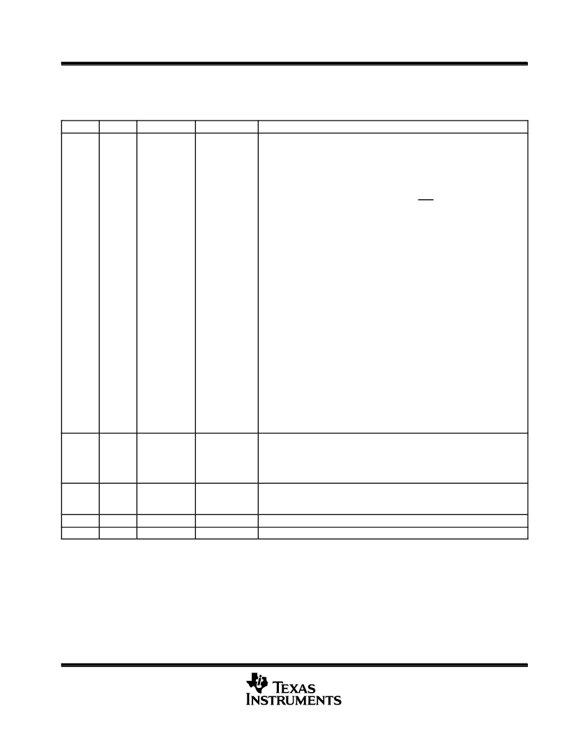
Table 15. XINTCNF2 Register Bit Definitions
BITS
TYPE
NAME
RESET
DESCRIPTION
1,0
R/W
Write
Buffer
Depth
0,0
The write buffer allows the processor to continue execution without waiting for
XINTF write accesses to complete. The write buffer depth is selectable as follows:
Depth
Action
00
No write buffering. The CPU will be stalled until the write
completes on the XINTF.
Note:
Default mode on reset (XRS).
01
The XINTF will buffer one word. The CPU is stalled until the
write cycle begins on the XINTF (there could be a read cycle
currently active on the XINTF).
10
One write will be buffered without stalling the CPU. The CPU
is stalled if a second write follows. The CPU will be stalled
until the first write begins its cycle on the XINTF.
11
Two writes will be buffered without stalling the CPU. The CPU
is stalled if a third write follows. The CPU will be stalled until
the first write begins its cycle on the XINTF.
The buffered access can be 8, 16, or 32 bits in length. Order of execution is
preserved, e.g., writes are performed in the order they were accepted. The
processor is stalled on XINTF reads until all pending writes are done and the read
access completes. If the buffer is full, any pending reads or writes to the buffer
will stall the processor.
The
“
Write Buffer Depth
”
can be changed; however, it is recommended that the
write buffer depth be changed only when the buffer is empty (this can be checked
by reading the
“
Write Buffer Level
”
bits). Writing to these bits when the level is not
zero may have unpredictable results.
2
R/W
CLKMODE
Mode
1
XCLKOUT divide by 2 mode. If this bit is set to 1, XCLKOUT is a divide by 2 of
XTIMCLK. If this bit is set to 0, XCLKOUT is equal to XTIMCLK. All bus timings,
irrespective of which mode is enabled, will start from the rising edge of XCLKOUT.
The default mode of operation on power up and reset is /2 mode.
3
R/W
CLKOFF
0
Turn XCLKOUT off mode. When this bit is set to 1, the XCLKOUT signal is turned
off. This is done for power savings and noise reduction. This bit is set to 0 on a
reset.
4
R
Reserved
1
Reserved
5
R
Reserved
0
Reserved
P
相關(guān)PDF資料 |
PDF描述 |
|---|---|
| TMP320F2810GHHMEP | Digital Signal Processors |
| TMX320F2810GHHS | DIGITAL SIGNAL PROCESSORS |
| TMP320F2810GHHS | DIGITAL SIGNAL PROCESSORS |
| TMX320F2810PGFA | DIGITAL SIGNAL PROCESSORS |
| TMP320F2810PGFA | DIGITAL SIGNAL PROCESSORS |
相關(guān)代理商/技術(shù)參數(shù) |
參數(shù)描述 |
|---|---|
| TMX320F2810GHHS | 制造商:TI 制造商全稱:Texas Instruments 功能描述:DIGITAL SIGNAL PROCESSORS |
| TMX320F2810PBKA | 制造商:TI 制造商全稱:Texas Instruments 功能描述:DIGITAL SIGNAL PROCESSORS |
| TMX320F2810PBKAEP | 制造商:TI 制造商全稱:Texas Instruments 功能描述:Digital Signal Processors |
| TMX320F2810PBKS | 制造商:TI 制造商全稱:Texas Instruments 功能描述:DIGITAL SIGNAL PROCESSORS |
| TMX320F2810PGFA | 制造商:TI 制造商全稱:Texas Instruments 功能描述:DIGITAL SIGNAL PROCESSORS |
發(fā)布緊急采購(gòu),3分鐘左右您將得到回復(fù)。