- 您現(xiàn)在的位置:買賣IC網(wǎng) > PDF目錄382649 > TMX320F2810PBKS (Texas Instruments, Inc.) DIGITAL SIGNAL PROCESSORS PDF資料下載
參數(shù)資料
| 型號(hào): | TMX320F2810PBKS |
| 廠商: | Texas Instruments, Inc. |
| 元件分類: | 數(shù)字信號(hào)處理 |
| 英文描述: | DIGITAL SIGNAL PROCESSORS |
| 中文描述: | 數(shù)字信號(hào)處理器 |
| 文件頁數(shù): | 29/103頁 |
| 文件大小: | 1341K |
| 代理商: | TMX320F2810PBKS |
第1頁第2頁第3頁第4頁第5頁第6頁第7頁第8頁第9頁第10頁第11頁第12頁第13頁第14頁第15頁第16頁第17頁第18頁第19頁第20頁第21頁第22頁第23頁第24頁第25頁第26頁第27頁第28頁當(dāng)前第29頁第30頁第31頁第32頁第33頁第34頁第35頁第36頁第37頁第38頁第39頁第40頁第41頁第42頁第43頁第44頁第45頁第46頁第47頁第48頁第49頁第50頁第51頁第52頁第53頁第54頁第55頁第56頁第57頁第58頁第59頁第60頁第61頁第62頁第63頁第64頁第65頁第66頁第67頁第68頁第69頁第70頁第71頁第72頁第73頁第74頁第75頁第76頁第77頁第78頁第79頁第80頁第81頁第82頁第83頁第84頁第85頁第86頁第87頁第88頁第89頁第90頁第91頁第92頁第93頁第94頁第95頁第96頁第97頁第98頁第99頁第100頁第101頁第102頁第103頁

TMS320F2810, TMS320F2812
DIGITAL SIGNAL PROCESSORS
SPRS174B
–
APRIL 2001
–
REVISED SEPTEMBER 2001
29
POST OFFICE BOX 1443
HOUSTON, TEXAS 77251
–
1443
timing registers (continued)
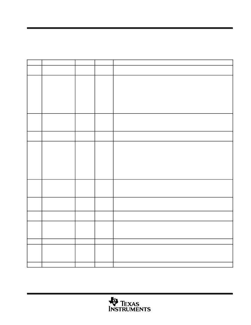
The individual timing parameters can be programmed into the XTIMING registers as described in Table 14.
Table 14. XTIMING0/1/2/6/7 Register Bit Definitions
BIT
NAME
ACCESS
RESET
DESCRIPTION
1:0
XWRTRAIL
R/W
1,1
Two-bit field that defines the write cycle trail period, in XTIMCLK cycles, from
0,1,2,3 (if X2TIMING bit is 0) or 0,2,4,6 (if X2TIMING bit is 1).
4:2
XWRACTIVE
R/W
1,1,1
Three-bit field that defines the write cycle active wait-state period, in XTIMCLK
cycles, from 0,1,2,3,4,5,6,7 (if X2TIMING bit is 0) or 0,2,4,6,8,10,12,14 (if
X2TIMING bit is 1).
Notes: 1. If the USEREADY bit is set to 1 (using XREADY),
then XWRACTIVE must be
≥
1.
2. The active period is by default 1 cycle. Hence the total active period
is 1 + XWRACTIVE value.
6:5
XWRLEAD
R/W
1,1
Two-bit field that defines the write cycle lead period, in XTIMCLK cycles, from 1,2,3
(if X2TIMING bit is 0) or 2,4,6 (if X2TIMING bit is 1).
Note:
XWRLEAD must be
≥
1.
Two-bit field that defines the read cycle trail period, in XTIMCLK cycles, from
0,1,2,3 (if X2TIMING bit is 0) or 0,2,4,6 (if X2TIMING bit is 1).
8:7
XRDTRAIL
R/W
1,1
11:9
XRDACTIVE
R/W
1,1,1
Three-bit field that defines the read cycle active wait-state period, in XTIMCLK
cycles, from 0,1,2,3,4,5,6,7 (if X2TIMING bit is 0) or 0,2,4,6,8,10,12,14
(if X2TIMING bit is 1).
Notes: 1. If the USEREADY bit is set to 1 (using XREADY),
then XRDACTIVE must be
≥
1.
2. The active period is by default 1 cycle. Hence the total active period
is 1 + XRDACTIVE value.
13:12
XRDLEAD
R/W
1,1
Two-bit field that defines the read cycle lead period, in XTIMCLK cycles, from 1,2,3
(if X2TIMING bit is 0) or 2,4,6 (if X2TIMING bit is 1).
Note:
XRDLEAD must be
≥
1.
When set, the XREADY signal can be used to further extend the active portion of
the cycle past the minimum defined by the XRDACTIVE and XWRACTIVE fields.
When cleared XREADY is ignored.
14
USEREADY
R/W
1
15
READYMODE
R/W
1
When set, the XREADY input is asynchronous. When cleared, the XREADY input
is synchronous.
17:16
Reserved
R/W
1,1
Reserved.
These two bits must always be written to as 1,1. Any other combination is reserved
and will result in incorrect XINTF behavior.
21:18
Reserved
R
0
Reserved
22
X2TIMING
R/W
1
This bit specifies the scaling factor of the LEAD, ACTIVE, TRAIL values in the
individual timing registers. If this bit is 0, the values are scaled 1:1. If this bit is 1,
the values are scaled 2:1 (doubled). The default mode of operation on power up
and reset is 2:1 scaling (doubled) mode.
31:23
Reserved
R
0
P
相關(guān)PDF資料 |
PDF描述 |
|---|---|
| TMP320F2810PBKS | DIGITAL SIGNAL PROCESSORS |
| TMP320F2810GHHA | DIGITAL SIGNAL PROCESSORS |
| TMX320F2810GHHMEP | Digital Signal Processors |
| TMP320F2810GHHMEP | Digital Signal Processors |
| TMX320F2810GHHS | DIGITAL SIGNAL PROCESSORS |
相關(guān)代理商/技術(shù)參數(shù) |
參數(shù)描述 |
|---|---|
| TMX320F2810PGFA | 制造商:TI 制造商全稱:Texas Instruments 功能描述:DIGITAL SIGNAL PROCESSORS |
| TMX320F2810PGFAEP | 制造商:TI 制造商全稱:Texas Instruments 功能描述:Digital Signal Processors |
| TMX320F2810PGFS | 制造商:TI 制造商全稱:Texas Instruments 功能描述:DIGITAL SIGNAL PROCESSORS |
| TMX320F2811GHHA | 制造商:TI 制造商全稱:Texas Instruments 功能描述:TMS320R2811, TMS320R2812 Digital Signal Processors |
| TMX320F2811GHHQ | 制造商:TI 制造商全稱:Texas Instruments 功能描述:TMS320R2811, TMS320R2812 Digital Signal Processors |
發(fā)布緊急采購,3分鐘左右您將得到回復(fù)。