- 您現(xiàn)在的位置:買賣IC網(wǎng) > PDF目錄382684 > TQ5M34 Analog IC PDF資料下載
參數(shù)資料
| 型號(hào): | TQ5M34 |
| 英文描述: | Analog IC |
| 中文描述: | 模擬IC |
| 文件頁(yè)數(shù): | 13/18頁(yè) |
| 文件大小: | 207K |
| 代理商: | TQ5M34 |
第1頁(yè)第2頁(yè)第3頁(yè)第4頁(yè)第5頁(yè)第6頁(yè)第7頁(yè)第8頁(yè)第9頁(yè)第10頁(yè)第11頁(yè)第12頁(yè)當(dāng)前第13頁(yè)第14頁(yè)第15頁(yè)第16頁(yè)第17頁(yè)第18頁(yè)

TQ5M34
Data Sheet
For additional information and latest specifications, see our website:
www.triquint.com
13
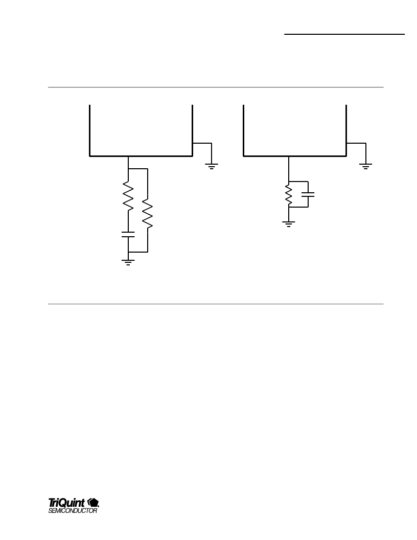
Here is an approximate equation for Rgic as a function of IF
stage Idd: Rgic ~ 0.6 / IDD_IF
Remember that due to the filter-mxer interaction, the final
Rgic may need to be changed to optimze performance once
LO power is applied.
GIC PIN
GIC PIN
Chip
GND
Chip
GND
0 to 5 ohms
20 to 60 ohms
20 to 60 ohms
sets IF
current
Zc bypass
at IF Freq
Zc bypass
at IF Freq
AC degen
sets IF
current
Figure 6: Two Recommended GIC Networks
IF Match Design:
The Mxer IF output (Pin 2) is an "open-drain" configuration,
allowing for flexibility in efficient matching to various filter
types and at various IF frequencies. An optimumlumped-
element-matching network must be designed for maximum
TQ5M34 conversion gain and mnimummatching network
loss.
When designing the IF output matching circuit, one has to
consider the output impedance (pin 3) of the IF Amplifier. It
will vary somewhat depending on the quiescent current and
the LO drive. The IF frequency can be tuned from45 to 400
MHz by varying component values of the IF output matching
circuit. The IF output pin also provides the DC bias for the
output FET.
In the user's application, the IF output is most commonly
connected to a narrow band SAW or crystal filter with
impedance from500 -1000
with 1 - 2 pF of capacitance. A
conjugate match to a higher filter impedance is generally less
sensitive than matching to 50
. When verifying or adjusting
the matching circuit on the prototype circuit board, the LO
drive should be injected at the nomnal power level (-4 dBm,
since the LO level does have an impact on the IF port
impedance.
There are several networks that can be used to properly
match the IF port to the SAW or crystal IF filter. The IF FET
current is applied through the IF output Pin 2, so the matching
circuit topology must contain either an RF choke or shunt
inductor.
相關(guān)PDF資料 |
PDF描述 |
|---|---|
| TQ8214 | Industrial Control IC |
| TQ8219 | Optoelectronic |
| TQ8223 | ATM/SONET Demultiplexer |
| TQ8224 | Industrial Control IC |
| TQ8318 | Telecommunication IC |
相關(guān)代理商/技術(shù)參數(shù) |
參數(shù)描述 |
|---|---|
| TQ5M44 | 制造商:TRIQUINT 制造商全稱:TriQuint Semiconductor 功能描述:RF Mixer IC |
| TQ6111BI | 制造商:未知廠家 制造商全稱:未知廠家 功能描述:Converter IC |
| TQ6111BV | 制造商:未知廠家 制造商全稱:未知廠家 功能描述:Converter IC |
| TQ6111D | 制造商:未知廠家 制造商全稱:未知廠家 功能描述:Converter IC |
| TQ6111M | 制造商:未知廠家 制造商全稱:未知廠家 功能描述:Converter IC |
發(fā)布緊急采購(gòu),3分鐘左右您將得到回復(fù)。