- 您現(xiàn)在的位置:買賣IC網(wǎng) > PDF目錄98302 > TSC2101IRGZRG4 (TEXAS INSTRUMENTS INC) SPECIALTY CONSUMER CIRCUIT, PQCC48 PDF資料下載
參數(shù)資料
| 型號: | TSC2101IRGZRG4 |
| 廠商: | TEXAS INSTRUMENTS INC |
| 元件分類: | 消費(fèi)家電 |
| 英文描述: | SPECIALTY CONSUMER CIRCUIT, PQCC48 |
| 封裝: | GREEN, PLASTIC, VQFN-48 |
| 文件頁數(shù): | 27/95頁 |
| 文件大小: | 1217K |
| 代理商: | TSC2101IRGZRG4 |
第1頁第2頁第3頁第4頁第5頁第6頁第7頁第8頁第9頁第10頁第11頁第12頁第13頁第14頁第15頁第16頁第17頁第18頁第19頁第20頁第21頁第22頁第23頁第24頁第25頁第26頁當(dāng)前第27頁第28頁第29頁第30頁第31頁第32頁第33頁第34頁第35頁第36頁第37頁第38頁第39頁第40頁第41頁第42頁第43頁第44頁第45頁第46頁第47頁第48頁第49頁第50頁第51頁第52頁第53頁第54頁第55頁第56頁第57頁第58頁第59頁第60頁第61頁第62頁第63頁第64頁第65頁第66頁第67頁第68頁第69頁第70頁第71頁第72頁第73頁第74頁第75頁第76頁第77頁第78頁第79頁第80頁第81頁第82頁第83頁第84頁第85頁第86頁第87頁第88頁第89頁第90頁第91頁第92頁第93頁第94頁第95頁
TSC2101
SLAS392D JUNE 2003 REVISED MAY 2005
www.ti.com
33
Analog Mixer
The analog mixer can be used to route the analog input selected for the ADC through an analog volume control
and then mix it with the audio DAC output. The analog mixer feature is available only if the single ended
microphone input or the AUX input is selected as the input to the ADC, not when the ADC input is configured
in fully-differential mode. This feature is available even if the ADC and DAC are powered down. The analog
volume control has a range from +12 dB to –34.5 dB in 0.5 dB steps plus mute and includes softstepping logic.
The internal oscillator is used for softstepping whenever the ADC and DAC are powered down.
Keyclick
A special circuit has been included for inserting a squarewave signal into the analog output signal path based
on register control. This functionality is intended for generating keyclick sounds for user feedback. Register
04H/Page 2 contains bits that control the amplitude, frequency, and duration of the squarewave signal. The
frequency of the signal can be varied from 62.5 Hz to 8 kHz and its duration can be programmed from 2 periods
to 32 periods. Whenever this register is written, the square wave is generated and coupled into the audio output.
The keyclick enable bit D15 of control register 04H/Page 2 is reset after the duration of a keyclick is played out.
This capability is available even when the ADC and DAC are powered down.
OPERATION—TOUCH SCREEN
A resistive touch screen works by applying a voltage across a resistor network and measuring the change in
resistance at a given point on the matrix where a screen is touched by an input stylus, pen, or finger. The change
in the resistance ratio marks the location on the touch screen.
The TSC2101 supports the resistive 4-wire configurations (see Figure 25). The circuit determines location in
two coordinate pair dimensions, although a third dimension can be added for measuring pressure.
The 4-Wire Touch Screen Coordinate Pair Measurement
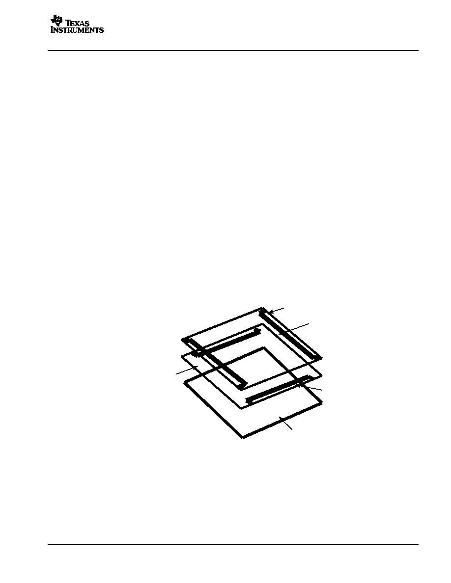
A 4-wire touch screen is constructed as shown in Figure 25. It consists of two transparent resistive layers
separated by insulating spacers.
Conductive Bar
Transparent Conductor (ITO)
Bottom Side
X+
X
Y+
Y
Transparent Conductor (ITO)
Top Side
Insulating Material (Glass)
ITO= Indium Tin Oxide
Silver Ink
Figure 25. 4-Wire Touch Screen Construction
The 4-wire touch screen panel works by applying a voltage across the vertical or horizontal resistive network.
The ADC converts the voltage measured at the point the panel is touched. A measurement of the Y position
of the pointing device is made by connecting the X+ input to an ADC, turning on the Y drivers, and digitizing
the voltage seen at the X+ input. The voltage measured is determined by the voltage divider developed at the
point of touch. For this measurement, the horizontal panel resistance in the X+ lead does not affect the
conversion due to the high input impedance of the ADC.
Voltage is then applied to the other axis, and the ADC converts the voltage representing the X position on the
screen. This provides the X and Y coordinates to the associated processor.
相關(guān)PDF資料 |
PDF描述 |
|---|---|
| TSC2101IRGZG4 | SPECIALTY CONSUMER CIRCUIT, PQCC48 |
| TSC2111IRGZR | 0.4 W, 1 CHANNEL, AUDIO AMPLIFIER, QCC48 |
| TSC2111IRGZT | 0.4 W, 1 CHANNEL, AUDIO AMPLIFIER, QCC48 |
| TSC2111IRGZRG4 | 0.4 W, 1 CHANNEL, AUDIO AMPLIFIER, QCC48 |
| TSC2111IRGZTG4 | 0.4 W, 1 CHANNEL, AUDIO AMPLIFIER, QCC48 |
相關(guān)代理商/技術(shù)參數(shù) |
參數(shù)描述 |
|---|---|
| TSC2101RGZG4 | 制造商:Texas Instruments 功能描述:AUD CODEC 2ADC / 2DAC 32BIT 48QFN - Rail/Tube |
| TSC2101RGZRG4 | 制造商:Texas Instruments 功能描述:AUD CODEC 2ADC / 2DAC 32BIT 48QFN - Tape and Reel |
| TSC2102 | 制造商:TI 制造商全稱:Texas Instruments 功能描述:PROGRAMMABLE TOUCH SCREEN CONTROLLER WITH INTEGRATED STEREO AUDIO DAC AND HEADPHONE AMPLIFIER |
| TSC21020F | 制造商:ATMEL 制造商全稱:ATMEL Corporation 功能描述:Rad. Hard 32/40-bit IEEE Floating Point DSP |
| TSC21020F-20MA | 制造商:未知廠家 制造商全稱:未知廠家 功能描述:32-Bit Digital Signal Processor |
發(fā)布緊急采購,3分鐘左右您將得到回復(fù)。