- 您現(xiàn)在的位置:買賣IC網(wǎng) > PDF目錄384045 > UPD72852 (NEC Corp.) MOS INTEGRATED CIRCUIT PDF資料下載
參數(shù)資料
| 型號: | UPD72852 |
| 廠商: | NEC Corp. |
| 英文描述: | MOS INTEGRATED CIRCUIT |
| 中文描述: | 馬鞍山集成電路 |
| 文件頁數(shù): | 31/48頁 |
| 文件大?。?/td> | 249K |
| 代理商: | UPD72852 |
第1頁第2頁第3頁第4頁第5頁第6頁第7頁第8頁第9頁第10頁第11頁第12頁第13頁第14頁第15頁第16頁第17頁第18頁第19頁第20頁第21頁第22頁第23頁第24頁第25頁第26頁第27頁第28頁第29頁第30頁當(dāng)前第31頁第32頁第33頁第34頁第35頁第36頁第37頁第38頁第39頁第40頁第41頁第42頁第43頁第44頁第45頁第46頁第47頁第48頁

Data Sheet S14920EJ3V0DS
31
μ
PD72852
Figure 4-7. Link Cancel Timing (After Hold)
00
11
00
ZZ
ZZ
ZZ
ZZ
ZZ
00
00
00
00
ZZ
ZZ
ZZ
ZZ
ZZ
00
ZZ
ZZ
ZZ
00
01
01
00
00
ZZ
ZZ
ZZ
ZZ
00
00
00
00
00
ZZ
PHY CTL0,CTL1
PHY D0-D7
Link CTL0,CTL1
Link D0-D7
4.8 Receive
This section shows the operation when the packet is received from the serial bus.
When the
μ
PD72852 detects DATA_PREFIX on the serial bus, it asserts receive to CTL and all of the D pins
assume the logic value of 1.
The
μ
PD72852 shows the speed code of the transfer rate ahead of the packet using bits D0-D7. Transmitting the
speed code with the speed signal is the protocol of the PHY/Link interface. The speed code is not included in the
CRC calculation.
The
μ
PD72852 continues to assert Receive to CTL until the packet is finally transmitted.
Idle is asserted to CTL, indicating completion of the packet transmission.
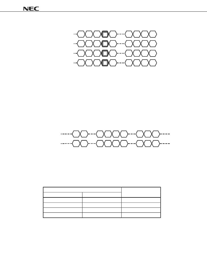
Figure 4-8. Receive Timing
00
10
10
10
10
10
00
00
FF
FF
D0
D1
D
n
00
PHY CTL0,CTL1
(Binary)
PHY D0-D7
(Hex)
10
SP
00
00
The packet transfer rate of the serial bus depends on the topology of the bus. The
μ
PD72852 checks if the node
can receive at the faster transfer rate. At this time, DATA_PREFIX
→
DATA_END is transmitted to the
μ
PD72852.
After DATA_PREFIX is transmitted to the Link, Receive from the serial bus is completed, asserting Idle.
Table 4-14 shows the speed code encoding.
Table 4-14. Speed Encoding
D0-D7
Data rate
Transmitted
Observed
00000000
00xxxxxx
S100
01000000
0100xxxx
S200
01010000
01010000
S400
11111111
11xxxxxx
Data Prefix
相關(guān)PDF資料 |
PDF描述 |
|---|---|
| UPD72852GB-8EU | MOS INTEGRATED CIRCUIT |
| UPD72870F1 | IEEE1394 1-CHIP OHCI HOST CONTROLLER |
| UPD72870FA2 | IEEE1394 1-CHIP OHCI HOST CONTROLLER |
| UPD72871F1 | IEEE1394 1-CHIP OHCI HOST CONTROLLER |
| UPD72871FA2 | IEEE1394 1-CHIP OHCI HOST CONTROLLER |
相關(guān)代理商/技術(shù)參數(shù) |
參數(shù)描述 |
|---|---|
| UPD74HC04C | 制造商:Panasonic Industrial Company 功能描述:IC |
| UPD750068GT-396 | 制造商:Renesas Electronics Corporation 功能描述: |
| UPD7507C189 | 制造商:Panasonic Industrial Company 功能描述:IC |
| UPD7508CU265 | 制造商:Panasonic Industrial Company 功能描述:IC |
| UPD75208 | 制造商:Panasonic Industrial Company 功能描述:IC |
發(fā)布緊急采購,3分鐘左右您將得到回復(fù)。